


4.6 Base cover assembly 4 Replacement Procedures
4.6 Base cover assembly
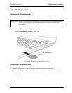
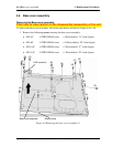
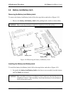
Removing the Base cover assembly
Click here to view caution on the disassembly/reassembly of the unit.
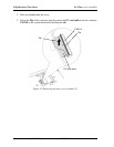
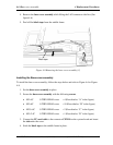
To remove the base cover assembly, follow the steps below and refer to Figure 4-6 to 4-8.
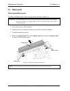
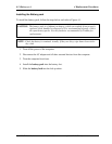
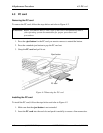
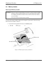
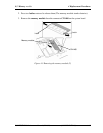
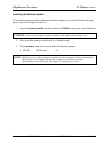
1. Remove the following screws securing the base cover assembly.
• M2×4C S-THIN HEAD screw ×4 (Described as “A” in the figure)
• M2×6C S-THIN HEAD screw ×10 (Described as “B” in the figure)
• M2.5×6C S-THIN HEAD screw ×2 (Described as “C” in the figure)
• M2×2.4C S-THIN HEAD screw ×1 (Described as “D” in the figure)
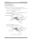
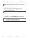
Base cover assembly
Middle frame
(B)
(B)
(B)
(B)
(B)
(B)
(B)
(C)
(C)
(A)
(A)
(A)
(A)
(D)
(B)
(B)
(B)
LAN connector
Figure 4-6 Removing the base cover assembly (1)
PORTÉGÉ R500 Maintenance Manual (960-634) [CONFIDENTIAL] 4-15