


4.6 Base cover assembly 4 Replacement Procedures
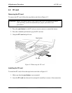
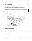
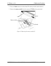
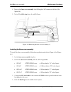
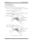
4. Remove the base cover assembly while lifting the LAN connector side first.(See
figure 4-6)
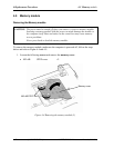
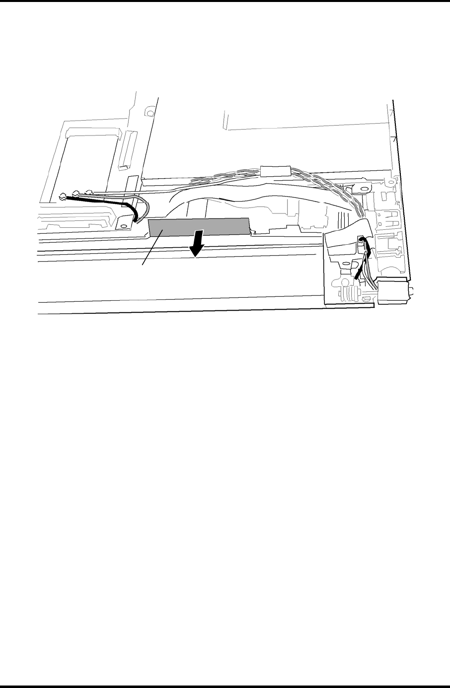
5. Peel off the black tape from the middle frame.
Black tape
Figure 4-8 Removing the base cover assembly (3)
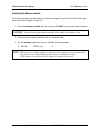
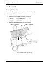
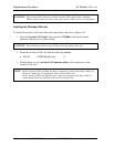
Installing the Base cover assembly
To install the base cover assembly, follow the steps below and refer to Figure 4-6 to Figure
4-8.
1. Set the base cover assembly in place.
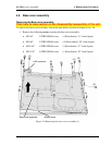
2. Secure the base cover assembly with the following screws.
• M2×4C S-THIN HEAD screw ×4 (Described as “A” in the figure)
• M2×6C S-THIN HEAD screw ×10 (Described as “B” in the figure)
• M2.5×6C S-THIN HEAD screw ×2 (Described as “C” in the figure)
• M2×2.4C S-THIN HEAD screw ×1 (Described as “D” in the figure)
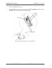
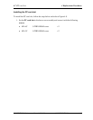
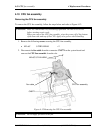
3. Connect the PC card cable to the connector CN2110 on the system board and insert
the tab under the cover.
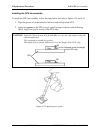
4. Stick the black tape to the middle frame in place.
PORTÉGÉ R500 Maintenance Manual (960-634) [CONFIDENTIAL] 4-17