


STE 58764
- -
2-19
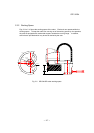
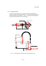
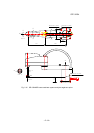
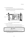
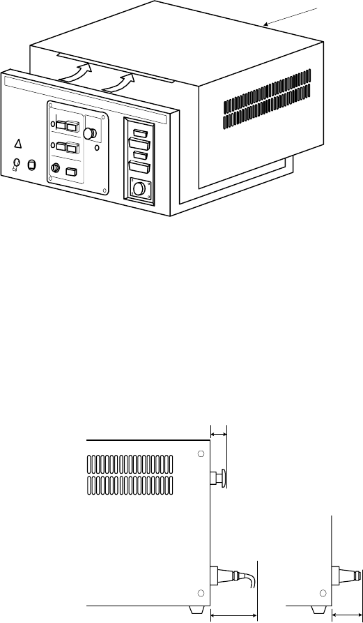
(3) The upper cover must be removed during maintenance. (See Fig. 2.21.)
Keep this in mind when installing the controller. Specifically, the controller should be
easily removable from the rack. Practically, be careful of the following points.
(a) Arrange the cables around the rear panel of the controller (so that the controller
can be removed).
(b) Arrange the cables between the controller and the control panel when the control
panel is separated (so that the controller can be removed).
(c) Connect all the cables in a position where the robot can be operated even if the
controller is removed from the rack.
Fig. 2.21 Upper cover
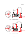
(4) When the controller is mounted on the rack, the weight of the controller should be
supported with the legs of the controller. Screw holes for rack mounting the
controller are used for securing the controller panel, and the weight of the controller
cannot be supported only with the screws.
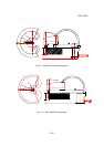
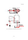
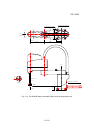
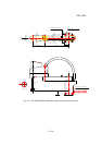
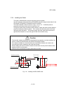
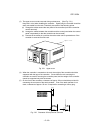
(5) On the front of the controller, a clearance of approx. 90 mm should be provided for
connecting the connector of the teach pendant. Even if the teach pendant is not
used, a clearance of approx. 50 mm is required for connecting a dummy plug.
Fig. 2.22 Clearance of front panel of controller
S
R
7
0
0
0
R
o
b
o
t
C
o
n
t
r
o
l
l
e
r
Upper cover
50mm
35mm
90mm