75
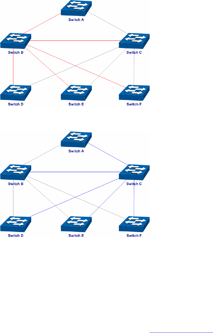
¾ The topology diagram of the two instances after the topology is stable
z For Instance 1 (VLAN101, 103 and 105), the red paths in the following figure are connected
links; the gray paths are the blocked links.
z For Instance 2 (VLAN102, 104 and 106), the blue paths in the following figure are connected
links; the gray paths are the blocked links.
¾ Suggestion for Configuration
z Enable TC Protect function for all the ports of switches.
z Enable Root Protect function for all the ports of root bridges.
z Enable Loop Protect function for the non-edge ports.
Enable BPDU Protect function or BPDU Filter function for the edge ports which are connected to
the PC and server.
Return to CONTENTS


