


2
SISTF10xx-130-LR(T)
24-hour Technical Support: 1-800-260-1312 -- International: 00-1-952-941-7600
NOTE: This device is intended to be grounded to a well-grounded
mounting surface such as a metal plate. Install the grounding wire prior
to connecting any other device.
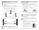
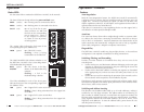
Ground the SISTF10xx-130-LR(T)
Grounding the device helps limit the effects of noise due to electromagnetic
interference (EMI). The grounding screw is located on the top panel next to
the terminal block.
To ground the SISTF10xx-130-LR(T):
1. Connect one end of the grounding wire (not included) to the grounding
screw by looping one end of the grounding wire under the star washer.
2. Tighten the grounding screw with a phillips-head screwdriver.
3. Connect the other end of the grounding wire to earth ground.
g
rounding screw
terminal block
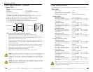
DIN-Rail
spring
mounting
plate
Step 1:
Step 2:
Installation
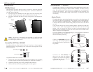
DIN-Rail Mount
The SISTF10xx-130-LR(T) Ethernet switch includes an aluminum DIN-Rail
mounting plate attached to the device’s back panel. To mount the SISTF10xx-
130-LR(T) onto a DIN-Rail:
1. Insert the top of the DIN-Rail into the upper slot of the mounting plate.
The stiff metal spring should be positioned behind the DIN-Rail.
2. Push down and rotate the device to snap it into place on the DIN-Rail as
shown.
techsupport@transition.com -- Click the “Transition Now” link for a live Web chat.
3
Installation -- Continued
The SISTF10xx-130-LR(T) is a plug-and-play unmanaged Ethernet switch with
Redundant Ring technology for better network reliability and faster recovery
time. The recovery time is less that 300 ms compared to 3 to 5 minutes for
commercial switches. Also, when one segment of the network gets
disconnected, the Redundant Ring automatically re-establishes network
connectivity.
Master Device
The Redundant Ring technology identifies one switch as the Ring Master of
the network, and then automatically blocks packets from traveling through
any of the network’s redundant loops. To designate one of the SISTF10xx-
130-LR(T) devices to be the network’s Ring Master, set switch 6 on that device
to “ON”.
If two or more devices are set to be the Ring Master, those devices with their
switch 6 set to “ON” auto-negotiate to determine which one is the Ring
Master. Also, if none of the devices are set to be the Ring Master, the
Redundant Ring technology chooses the device that has the smallest MAC
address range to be the Ring Master.
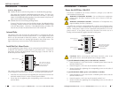
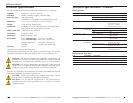
The actual topology of the Redundant Ring (i.e., which segment is blocked) is
determined by the number of
devices that make up the ring:
If there is an odd number of devices
in the ring, the backup segment is
the segment directly opposite the
Ring Master:
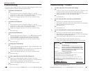
If there is an even number of
devices in the ring, the backup
segment is one of the two segments
connected to the unit directly
opposite the Ring Master:
TX
TX
PWR 1
PWR 2
FAULT
Redundant Ring Industrial Switch
RX
RX
10/100BASE-TX
100BASE-FX
100M
100M
RING
MASTER
TX
TX
PWR 1
PWR 2
FAULT
Redundant Ring Industrial Switch
RX
RX
10/100BASE-TX
100BASE-FX
100M
100M
RING
MASTER
TX
TX
PWR 1
PWR 2
FAULT
Redundant Ring Industrial Switch
RX
RX
10/100BASE-TX
100BASE-FX
100M
100M
RING
MASTER
master switch
in the network
network's backup segment
TX
TX
PWR 1
PWR 2
FAULT
Redundant Ring Industrial Switch
RX
RX
10/100BASE-TX
100BASE-FX
100M
100M
RING
MASTER
network's backu
p
segments
TX
TX
PWR 1
PWR 2
FAULT
Redundant Ring Industrial Switch
RX
RX
10/100BASE-TX
100BASE-FX
100M
100M
RING
MASTER
TX
TX
PWR 1
PWR 2
FAULT
Redundant Ring Industrial Switch
RX
RX
10/100BASE-TX
100BASE-FX
100M
100M
RING
MASTER
TX
TX
PWR 1
PWR 2
FAULT
Redundant Ring Industrial Switch
RX
RX
10/100BASE-TX
100BASE-FX
100M
100M
RING
MASTER
master switch
in the network