


4
SISTF10xx-130-LR(T)
24-hour Technical Support: 1-800-260-1312 -- International: 00-1-952-941-7600
Installation -- Continued
CAUTION: Disconnect the SISTF10xx-130-LR(T) from the DC power
source BEFORE installing and/or wiring the device.
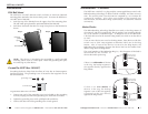
Install the Fiber Cable
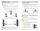
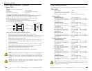
To build the Redundant Ring network, connect the SISTF10xx-130-LR(T)
devices using the two fiber ports labeled “4” and “5”. The fiber links can be
connected between two adjacent devices using any of the following
combinations:
A: Port 4 of one device connected to port 4 of the adjacent device.
B: Port 4 of one device connected to port 5 of the adjacent device.
C: Port 5 of one device connected to port 5 of the adjacent device.
When connecting the fiber links, make sure the transmit (TX) port on one
device is connected to the receive (RX) port on the adjacent device as shown:
TX
TX
PWR 1
PWR 2
FAULT
Redundant Ring Industrial Switch
RX
RX
10/100BASE-TX
100BASE-FX
100M
100M
RING
MASTER
TX
TX
PWR 1
PWR 2
FAULT
Redundant Ring Industrial Switch
RX
RX
10/100BASE-TX
100BASE-FX
100M
100M
RING
MASTER
TX
TX
PWR 1
PWR 2
FAULT
Redundant Ring Industrial Switch
RX
RX
10/100BASE-TX
100BASE-FX
100M
100M
RING
MASTER
port 5
p
ort 5
p
ort 4
port 4
port 4
port 5
A
B
C
Connect the fiber
cable to the
SISTF10xx-130-LR(T)
as shown.
Connect the fiber
cable to the adjacent
SISTF10xx-130-LR(T)
as shown
RX
TX
RX
TX
NOTE: Calculate the maximum possible current in each power wire and
signal wire. Observe all electrical codes for maximum current allowed.
If the current goes above the maximum ratings, the wiring would
overheat, causing serious damage to the network equipment.
CAUTION: Wear a grounding device and observe electrostatic discharge
precautions when setting the dip switches. Failure to observe this caution
could result in damage to, and failure of, the SISTF10xx-130-LR(T).
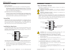
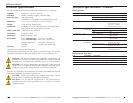
Set the Dip Switches
• The dip switches are located on the top panel of the device.
• Use a small flat blade screwdriver or a similar device to set the switches.
NOTE: To activate the updated switch setting, cycle the power to the
SISTF10xx-130-LR(T) by turning off the power, then turning it back on.
Switches 1 - 5: Port Alarm
The port alarm feature is used to determine faults at the copper or fiber ports.
• Switches 1, 2, and 3 correspond to copper ports 1, 2, and 3, respectively.
• Switches 4 and 5 correspond to fiber ports 4 and 5, respectively.
on: Enables the corresponding port alarm.
If the link for that port fails (or if a
power supply input fails), the internal
relay forms an open circuit and the
FAULT LED lights up.
off: Disables the corresponding port
alarm. The internal relay forms a
closed circuit and the FAULT LED
remains off.
techsupport@transition.com -- Click the “Transition Now” link for a live Web chat.
5
PORT
ALARM
RING
MASTER
DIPON
1
P1
2
P2
3
P3
4
P4
5
P5
6
RM
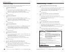
RJ-45 port
on the other device
(PLC, work station, etc.)
RJ-45 ports on the
SISTF10xx-130-LR(T)
Installation -- Continued
Install the Copper Cable
The AutoCross feature allows either straight-through (MDI) or crossover (MDI-
X) copper cable to be used when connecting devices via the RJ-45 port.
1. Locate or build 10Base-T or 100Base-TX copper cables with male, RJ-45
connectors installed at both ends.
2. Connect the RJ-45 connector at one end of the cable to the RJ-45 port on
the SISTF10xx-130-LR(T).
3. Connect the RJ-45 connector at the other end of the cable to the RJ-45
port on the other device (PLC, workstation, etc.).