


10
SISTF10xx-130-LR(T)
24-hour Technical Support: 1-800-260-1312 -- International: 00-1-952-941-7600
Cable Specifications -- Continued
Copper Cable
Category 5: (minimum requirement)
Gauge: 24 to 22 AWG
Attenuation: 22.0 dB /100m @ 100 MHz
Maximum Cable Distance: 100 meters
• Straight-through OR crossover cable may be used.
• Shielded twisted-pair (STP) OR unshielded twisted-pair (UTP) may be used
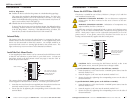
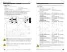
• Pins 1&2 and 3&6 are the two active pairs in an Ethernet network .
• RJ-45 Pin-out: Pin 1 = TD+, Pin 2 = TD-, Pin 3 = RD+, Pin 6 = RD-
• Use only dedicated wire pairs for the active pins:
(e.g., blue/white & white/blue, orange/white & white/orange, etc.)
• Do not use flat or silver satin wire.
Crossover Cable
1
2
3
6
Straight-Through Cable
Twisted Pair #1
Twisted Pair #1
Twisted Pair #2
Twisted Pair #2
1
2
3
6
1
2
3
6
1
2
3
6
Please note the following when wiring the network:
• Signal lines must not be directly connected to outdoor wiring.
• Use separate paths to route the power wiring and the signal wiring. If
power wiring and signal wiring paths must cross, make sure the wires are
perpendicular at the intersection point.
• Do not run signal wiring and power wiring in the same wire conduit. To
avoid interference, wires with different signal characteristics should also
be routed separately.
• Use the type of signal transmitted through a wire to determine which
wires should be kept separate. The rule of thumb is that wiring with
similar electrical characteristics can be bundled together.
• Keep input wiring and output wiring separate.
• Where necessary, label the wiring to all devices in the network.
NOTE: This device has been evaluated as EEx nC IIC T4 equipment
under DEMKO Certificate No. 03 ATEX 0324537U. Each module is
suitable for use in Zone 2 Explosive Atmospheres. The device must be
installed in a minimum IP 54 enclosure as defined in IEC 60529 and EN
60529.
NOTE: This unit is a building-in type. The installation into a certain end
equipment shall comply with fire enclosure request of IEC
60950/EN60950 or similar sentence.
11
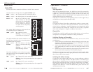
techsupport@transition.com -- Click the “Transition Now” link for a live Web chat.
Cable Specifications
The physical characteristics must meet or exceed IEEE 802.3™ specifications.
Fiber Cable
Bit Error Rate: <10-9
Single mode fiber (recommended): 9 µm
Multimode fiber (recommended): 62.5/125 µm
Multimode fiber (optional): 100/140, 85/140, 50/125 µm
Standard Models
SISTF1011-130-LR 1300 nm multimode
Fiber Optic Transmitter Power: min: -20.0 dBm max: -14.0 dBm
Fiber Optic Receiver Sensitivity: min: -36.0 dBm max: -32.0 dBm
Link Budget: 16.0 dB
SISTF1012-130-LR 1310 nm single mode
Fiber Optic Transmitter Power: min: -15.0 dBm max: -6.0 dBm
Fiber Optic Receiver Sensitivity: min: -34.0 dBm max: -32.0 dBm
Link Budget: 19.0 dB
SISTF1013-130-LR 1300 nm multimode
Fiber Optic Transmitter Power: min: -20.0 dBm max: -14.0 dBm
Fiber Optic Receiver Sensitivity: min: -36.0 dBm max: -32.0 dBm
Link Budget: 16.0 dB
SISTF1014-130-LR 1310 nm single mode
Fiber Optic Transmitter Power: min: -15.0 dBm max: -6.0 dBm
Fiber Optic Receiver Sensitivity: min: -34.0 dBm max: -32.0 dBm
Link Budget: 19.0 dB
Extended Temperature Models
SISTF1011-130-LRT 1300 nm multimode
Fiber Optic Transmitter Power: min: -20.0 dBm max: -14.0 dBm
Fiber Optic Receiver Sensitivity: min: -36.0 dBm max: -32.0 dBm
Link Budget: 16.0 dB
SISTF1012-130-LRT 1310 nm single mode
Fiber Optic Transmitter Power: min: -15.0 dBm max: -6.0 dBm
Fiber Optic Receiver Sensitivity: min: -34.0 dBm max: -32.0 dBm
Link Budget: 19.0 dB
SISTF1013-130-LRT 1300 nm multimode
Fiber Optic Transmitter Power: min: -20.0 dBm max: -14.0 dBm
Fiber Optic Receiver Sensitivity: min: -36.0 dBm max: -32.0 dBm
Link Budget: 16.0 dB
SISTF1014-130-LRT 1310 nm single mode
Fiber Optic Transmitter Power: min: -15.0 dBm max: -6.0 dBm
Fiber Optic Receiver Sensitivity: min: -34.0 dBm max: -32.0 dBm
Link Budget: 19.0 dB
NOTE: The fiber optic transmitters on this device meet Class I Laser
safety requirements per IEC-825/CDRH standards and comply with 21
CFR1040.10 and 21CFR1040.11.