


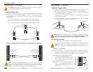
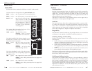

V2-
V1-
V1+
V2+
PWR2
FAULT
PWR1
The screws to secure
the wires are located
on the side of the
terminal block.
fault contacts
6
SISTF10xx-130-LR(T)
24-hour Technical Support: 1-800-260-1312 -- International: 00-1-952-941-7600
Install the Port Alarm Device
A user-supplied port alarm device can be connected to the SISTF10xx-130-LR
to alert the user whenever a power fault or a port fault occurs. At least one
port alarm switch or the Ring Master switch (see page 5) must be “ON” to
enable the port alarm feature.
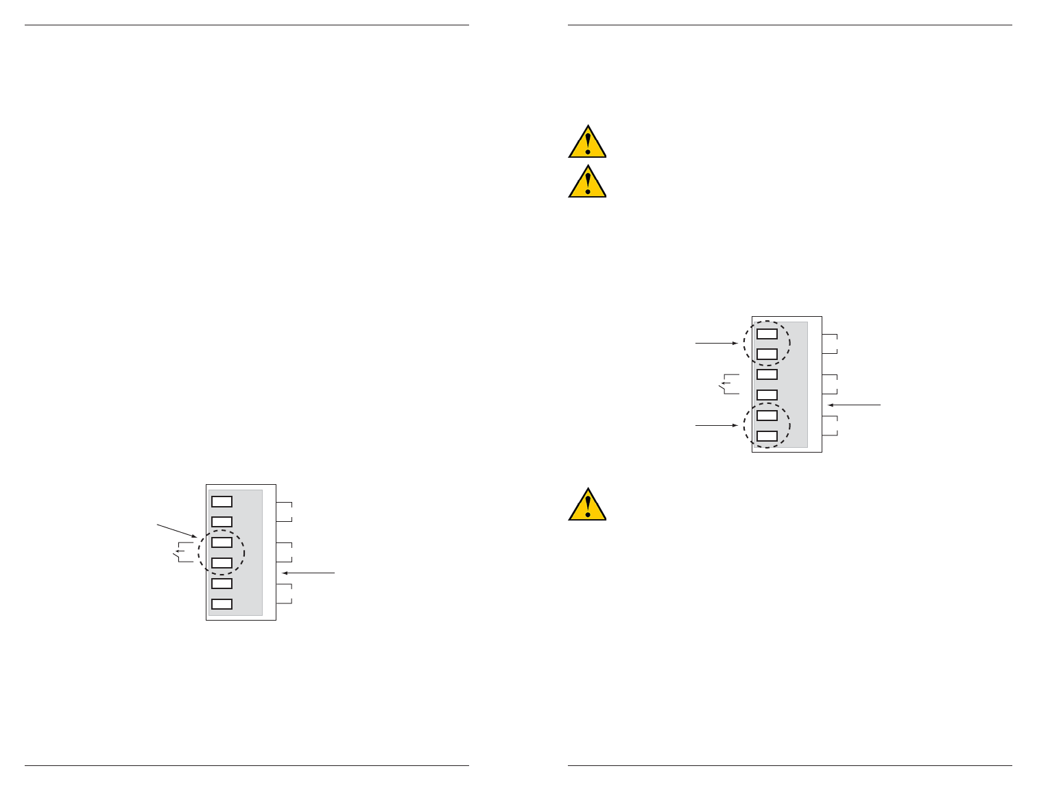
The contacts for the fault alarm are on the 6-contact terminal block, located
on the top panel of the SISTF10xx-130-LR(T). To install a port alarm device:
1. Insert the two wires from the user-supplied port alarm device into the two
terminals marked “FAULT” on the 6-contact terminal block.
2. Secure the wire by tightening the corresponding screw on the side of the
terminal block.
Installation -- Continued
Switch 6: Ring Master
on: Enables the device to be the Ring Master in a Redundant Ring topology.
This setting also enables the Redundant Ring break alarm. If a link in the
Redundant Ring breaks (and if the SISTF10xx-130-LR(T) is the Ring
Master in the Redundant Ring topology), then the internal relay forms an
open circuit and the FAULT LED lights up.
off: Disables the device from being the Ring Master.
If none of the devices are set to be the Ring Master, the Redundant Ring
technology chooses the device that has the smallest MAC address range
to be the Ring Master. However, if the Redundant Ring is broken, the
internal relay remains closed and the FAULT LED remains off.
Internal Relay
The internal relay that activates the alarm feature is connected to the two
middle contacts on the 6-contact terminal block. A user-supplied fault alarm
device can be connected to these fault contacts. An example would be to
connect the fault circuit to a warning light located in the control room. The
light can be set up to turn on when a fault is detected (see below).
techsupport@transition.com -- Click the “Transition Now” link for a live Web chat.
7
Installation -- Continued
Power the SISTF10xx-130-LR(T)
This device is suitable for use in Class I, Division 2, Groups A, B, C and D or
non-hazardous locations only.
WARNING: EXPLOSION HAZARD - Do not disconnect equipment
unless power has been removed or the area is known to be non-
hazardous.
WARNING: EXPLOSION HAZARD - Substitution of components may
impair suitability for Class I, Division 2.
The SISTF10xx-130-LR(T) is designed for both a primary and a backup power
supply via the 6-contact terminal block, located on the top panel of the
device. Both power inputs can be connected simultaneously to live DC
power sources. If one power source fails, the other live source acts as a
backup, and automatically supplies the device with power.
CAUTION: Before connecting the SISTF10xx-130-LR(T) to the 12-48
VDC power source, ensure the power source voltage is stable.
To provide PRIMARY (PWR1) power to the SISTF10xx-130-LR(T):
1. Insert the positive (+) DC wire from the 12-48VDC power source into the
terminal marked “V1+”.
2. Insert the negative (-) DC wire into the terminal marked “V1-”.
3. Secure the wires by tightening the corresponding screws on the side of
the terminal block.
To provide BACKUP (PWR2) power to the SISTF10xx-130-LR(T):
1. Insert the positive (+) DC wire from the 12-48VDC power source into the
terminal marked “V2+”.
2. Insert the negative (-) DC wire into the terminal marked “V2-”.
3. Secure the wires by tightening the corresponding screws on the side of
the terminal block.
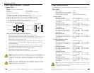
V2-
V1-
V1+
V2+
PWR2
FAULT
PWR1
V1, V2 INPUTS
12-48 VDC
The screws to secure
the wire are located
on the side of the
terminal block.
backup power
contacts
p
rimary power
contacts
6-contact terminal block