


SISTG10xx-111-LR(T) Industrial Media Converter Transition Networks
24-Hour Technical Support: 1-800-260-1312 International: 00-1-952-941-7600
17
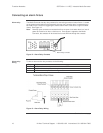
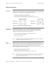
Connecting an alarm fixture, continued
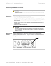
Fault indications
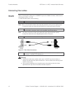
Wire the relay contacts to any warning light or audible alarm in the control room as shown in
Figure 14. When a fault occurs, the relay contacts open, stopping the flow of current through
the contact circuit. This will disable the external alarm or turn OFF a light, indicating a fault.
An alarm will occur under the following conditions:
• Power failure to either of the Media Converter power inputs:
o Power wires are disconnected, power source malfunction
o Input power is out of this range: 12 – 48VDC
Figure 14: Alarm Relay Contacts
Note: DIP switch #1 (Power alarm) must be enabled [ON] for the contact relay circuitry to
work as described in the manual. Fault notification will not take place if the power
alarm switch is disabled [OFF].