


SISTP10xx-141-LR(T) Industrial PoE Switch Transition Networks
24-Hour Technical Support: 1-800-260-1312 International: 00-1-952-941-7600
15
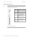
Connecting an alarm fixture
Alarm relay
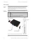
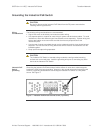
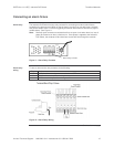
The Industrial PoE Switch has dry relay contacts for connecting an external alarm fixture.
Located on the green terminal block on the top panel, the relay has “normally open” contacts
that can be wired to form a circuit for triggering an external alarm when a fault occurs (light or
audible alarm). See Figure 11.
Note: Normally open contacts are contacts that form an open circuit when there is a loss of
power to the device or when a fault occurs. Once power is applied to the Industrial
PoE Switch, the contacts will be closed and current will flow through the contacts.
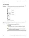
Figure 11: Alarm Relay Contacts
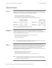
Alarm relay
wiring
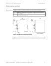
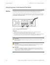
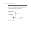
To wire an alarm to the relay contacts, do the following:
Step Action
1. Verify that the external power source is turned OFF.
2. Strip the wires as required.
3. Wire the alarm relay as shown in Figure 12.
Figure 12: Alarm Relay Wiring
Continued on next page
Alarm Relay Contacts