


SISTP10xx-141-LR(T) Industrial PoE Switch Transition Networks
24-Hour Technical Support: 1-800-260-1312 International: 00-1-952-941-7600
19
Light Emitting Diodes (LEDs)
LEDs
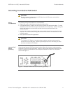
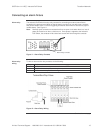
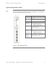
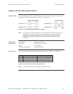
The Industrial PoE Switch has LED indicators located on its front panel. The LEDs present at-
a-glance network status, and provide real-time connectivity information. Figure 17 shows the
LEDs and a chart that explains the function of each.
LED Description
P1 Green = input power present on PWR1
input
P2 Green = input power present on PWR2
input
FAULT Red = Loss of either power input
LNK/ACT
(Fiber port)
Green = fiber link
Green (blinking) = fiber port is receiving
link pulses or data from a
100Base-FX compliant port
PWR FWD 1-4 Green = PoE power being supplied to
powered device (PD)
Off = No PoE power being output on
port
LNK/ACT
(UTP port)
[upper LED]
Green = UTP link
Green (blinking) = UTP port is receiving
link pulses or data from a
10/100Base-TX compliant port
Full Duplex /
Collision
(UTP port)
[lower LED]
Yellow = Full duplex link
Yellow (blinking) = collisions occurring
Off = half duplex or no link
Figure 17: LEDs and Description Chart