


23 June 2005 HE104MAN-V8 Manual
Tri-M Engineering Tel: 800.665.5600, 604.945.9565
1407 Kebet Way, Unit 100 Fax: 604.945.9566
Port Coquitlam, BC V3C 6L3 E-mail: info@tri-m.com
Canada Web site: www.tri-m.com
9
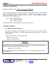
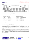
2.3.2 Output Power Connector
Output power is available for non-PC/104 use via connector CN2.
- Terminal 1: +5VDC output
- Terminal 2: Common
- Terminal 3: +12VDC
- Terminal 4: -12VDC output (optional)
- Terminal 5: -5VDC output (optional)
2.3.3 Battery Power Connector (Optional)
Batteries are connected to the screw terminal block, CN3. The HE104 accepts DC battery
voltages in the range of 6.5V to 40DVC through the Battery Power Connector. Two external
signals can be connected to the battery terminal block for use by add-on modules plugged into
the mezzanine header connectors. Connect to the HE104 Battery Terminal Block as follows:
-Terminal 1: Common of battery
-Terminal 2: Positive Battery Terminal
-Terminal 3: External signal 1
-Terminal 4: External signal 2
Note: When Optional Plug-IN Boost regulator (VR3) is ordered, batteries or external signals
cannot be connected to CN3. See section 2.3.4
2.3.4 Onboard PC “Boost” Adaption (Optional)
An optional converter Boost pump (model NMH05XXS, XX=output voltage, + 5V, +9V, +12V,
+15V) can be installed in location VR3 to provide custom output voltages. The NMH charge
pumps have an isolated positive and negative output and a maximum 2-watt capacity. A
minimum load of 10 percent is required for proper operation. By connecting the charge pump to
other voltages, the user can create more or less supplies, as well as elevated and negative
voltages (i.e.: The charge pump “0V” is not connected to the HE104 common).
- Terminal 1: Common of battery
- Terminal 2: -V output
- Terminal 3: 0V
- Terminal 4: +V output