


23 June 2005 HE104MAN-V8 Manual
Tri-M Engineering Tel: 800.665.5600, 604.945.9565
1407 Kebet Way, Unit 100 Fax: 604.945.9566
Port Coquitlam, BC V3C 6L3 E-mail: info@tri-m.com
Canada Web site: www.tri-m.com
14
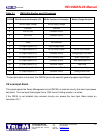
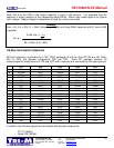
Table 2.1 PM104 Pin Number and I/O Functions
IC3 PIN#
PM104 Microcontroller Description (IC3)
HE104 Function or Connection Battery Charger Function
1
PM104 Supply Voltage HE104 Supply Voltage
2
Common Common
3
PC0 (PC out) Connector CN4-3
4
PCI (Pc in) Connector CN4-4
5
plus5V input/output No connection
6
Reset No connection
7
P0 (Input/Output Pin 0) Input Voltage Status
8
P1 (Input/Output Pin 1) HE104 On/Off Control HE104 On/Off control
9
P2 (Input/Output Pin 2) Connector CN6-8 Analog/Digital Chip Select
10
P3 (Input/Output Pin 3)* Int2, Connector CN6-7* Spare* Input/Output
11
P4 (Input/Output Pin 4) Connector CN6-6 Data Input/Output Line
12
P5 (Input/Output Pin 5) Connector CN605 Data Clock
13
P6 (Input/Output Pin 6)* Int1, Connector CN6-4* Spare* Input/Output
14
P7 (Input/Output Pin 7) Connector CN6-3 Analog Current Limit
*If Interrupt function is not used, this PM104 line can be used for general purpose Input/Output.
2.9 Low Input Alarm
This output signals the Power Management circuit (PM104) or external circuitry that main input power
has failed. The Low Input Alarm signal has a 100K current limiting resistor in a series.
If the PM104 is not installed, then external circuitry can access the Low Input Alarm output on
connector IC3-7.