


23 June 2005 HE104MAN-V8 Manual
Tri-M Engineering Tel: 800.665.5600, 604.945.9565
1407 Kebet Way, Unit 100 Fax: 604.945.9566
Port Coquitlam, BC V3C 6L3 E-mail: info@tri-m.com
Canada Web site: www.tri-m.com
12
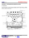
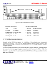
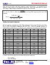
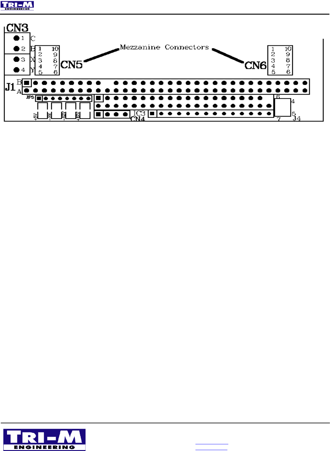
Figure 2.3, HE104 Mezzanine Connectors
Connector CN5 Pinout Connector CN6 Pinout
1. +5V 10. +5V 1. PM104-P1 10. Main Pwr. Input
2. Common 9. Common 2. Common 9. Common
3. +Battery Input 8. Main Pwr Input 3. PM104-P7 8. PM104-P2
4. Ext. Signal 1 7. +12V 4. PM104-P6 7. PM104-P3
5. Ext. Signal 2 6. -5V 5. PM104-P5 6. PM104-P4
2.7 PC/104 Bus Interrupts (Optional)
Interrupts to the PC/104 bus require the installation of the optional power management
mircrocontroller (PM104). The PM104 can be programmed to provide indication of loss of input
power, low battery voltage or to provide indication to the PC/104 CPU to begin an orderly shutdown
of program operation.
Two separate interrupt requests can be generated and each interrupt request will remain active until
the cause of the interrupt request returns to normal. Interrupt Int1 can be set to IRQ6 or IRQ7, while
interrupt Int2 can be set to IRQ4 or IRQ5 by installing an appropriate jumper on jumper selections
block J4. Jumper block J4 is located adjacent to the PC/104 bus on the opposite side where the
power LEDs are located.