


23 June 2005 HE104MAN-V8 Manual
Tri-M Engineering Tel: 800.665.5600, 604.945.9565
1407 Kebet Way, Unit 100 Fax: 604.945.9566
Port Coquitlam, BC V3C 6L3 E-mail: info@tri-m.com
Canada Web site: www.tri-m.com
28
‘D1 = 0, D0 = 0 channel 0 input, pin3 of connector CN3
‘D1 = 0, D0 = 1 channel 1 input, pin4 of connector CN3
‘1. on max cell voltage
‘2. on time
‘3. –ve delta V
‘4. cell temperature
next TCnt
let D1 = 0
let D0 = 0
gosub Convert ‘Get battery charging voltage
let Batt_V =AD
‘debud “charge”
if AD> BattV_Max then Batt_Chrg_Term
Chrg_Time = Chrg_Time + 1
If Chrg_Time > Chrg_Time_Max then Batt_Chrg_Term ‘Used maximum charge time
If AD < Batt_Peak then Batt_DeltaV
Let AD =AD +Neg_DeltaV
If AD <Batt_Peak then Batt_Chrg_Term ‘Detected negative deltaV in battery pack
**Insert battery pack temperature code here**
goto Chrg_Lp ‘Continue until charging terminated
Batt_Chrg_Term:
PWM Chrg_ Limit, 0.50 ‘turn off charge current
Let Bat1_Chrg = 1 ‘Indicate battery has been charged
Goto Main_Batt1
Convert:
ADC Interface Pins
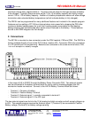
-The LTC 1594 uses a four-pin interface, consisting of chip-select, clock data input and data output.
In this application, we tie the data lines together and connect to the PM104 pin designated DIO.
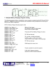
Here’s where the conversion occurs. The PM104 first sends the setup bits to the LTC1594, then
clocks in two bits followed by (sample time), one null bit (a dummy bit that always reads 0, followed
by the conversion data.
High CS1 ‘ Deactivate the ADC to begin
High CLK ‘ Clock data on rising edge, so start with CLK high
High Dio
Pulsout CLK.2
Low DIO
Pulsout CLK.2
Let DIOp = D1 ‘next bit of command
Pulseout CLK.2