23 June 2005 HE104MAN-V8 Manual
Tri-M Engineering Tel: 800.665.5600, 604.945.9565
1407 Kebet Way, Unit 100 Fax: 604.945.9566
Port Coquitlam, BC V3C 6L3 E-mail: info@tri-m.com
Canada Web site: www.tri-m.com
29
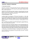
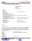
Let DIOp =D0 ‘next bit of command
Pulsout CLK.2 ‘Activate the LTC1594
Low CS1 ‘Get ready for input from LTC 1594
Input DIO
Pulsout CLK.2 ‘Dummy statement for delay
Input DIO ‘Sampling requires two clocks
Pulsout CLK.2
Let AD = 0 ‘Clear old ADC result.
For Adbits = 1 to 13 ‘Get null bit + 12 data bits.
Pulsout CLK.2 ‘Clock next data bit in.
Let AD = AD*2 +DIOp ‘Shift AD left, add new data bit.
Next Adbits ‘Get next data bit.
High CS1 ‘Turn off the ADC
Return ‘Return to program.
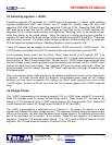
‘D1 = 1, D0 = 0 channel 2 input, monitors input voltage of battery regulator
‘D1 = 1, D0 =1 channel 3 input, monitors battery charging current
‘Note: channel 0 is usually jumpered to CN3 term2 for monitoring battery voltage
‘Note: channel 2 tracks main power input when greater than battery voltage
‘Note: channel 2 approx. 0.6V less than battery voltage when main input less than battery
voltage.
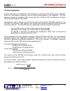
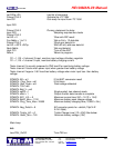
SYMBOL AD = w1 12-bit ADC conversion result
SYMBOL Chrg Time = w2 16-bit timer
SYMBOL Batt_Peak = w3 Peak voltage detected
SYMBOL TCnt =b8
SYMBOL Batt_V = w5
SYMBOL sglDif = 1 Single-ended, two-channel mode.
SYMBOL msbf = 1 Output 0s after data transfer is complete.
SYMBOL AO1_LVL = 5 Maximum current level (50 = 1A 75 = 1.5A)
SYMBOL BattV_Max = 1100 Maximum battery pack charge voltage
SYMBOL Chrg_Time_Max =10800 Maximum battery charging time (10,800 = 3hr.)
SYMBOL Neg_DeltaV = 8 AD convertor points for –deltaV (74pt/V IE
0.2V=18pts).
SYMBOL Trickle_LVL = 0 Trickle Charge Level (12 =.25A) See below:
SYMBOL BattV_Min = 740 Minimum battery voltage (10V)
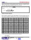
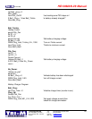
Main Loop
Init:
Low PSU_OnOff ‘Turn PSU on


