


23 June 2005 HE104MAN-V8 Manual
Tri-M Engineering Tel: 800.665.5600, 604.945.9565
1407 Kebet Way, Unit 100 Fax: 604.945.9566
Port Coquitlam, BC V3C 6L3 E-mail: info@tri-m.com
Canada Web site: www.tri-m.com
27
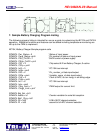
7. Sample Battery Charging Program Listing
The following program listing is intended for use as a guide to customizing the BC104 and PM104
operation. Additional functions and features can be added including temperature monitoring are
left up to the OEM to implement.
BC104, Battery Charger Sample program code
SYMBOL Pwr_Status = 0 ‘ Status of input power
SYMBOL Pwrp_Status =pin0 ‘ Pin number of status of input power
SYMBOL PSU_On/Off = 1 ‘OnOff control of power supply
SYMBOL PSUp_OnOff = pin1
SYMBOL CS1 = 2 ‘ Chip select A/D on Battery Charger; 0=active
SYMBOL CS1p = pin2
SYMBOL Int2 = 3 ‘ PC/104 bus interrupt
SYMBOL Int2p = pin3
SYMBOL DIO = 4 ‘ Pin_number_of data input/output.
SYMBOL DIOp = pin4 ‘ Variable_name_of date input/output.
SYMBOL CLK = 5 ‘ Clock to ADC; out on rising, in on falling edge.
SYMBOL CLKp = pin5
SYMBOL Int1 = 6 ‘ PC/104 bus interrupt
SYMBOL Intp = pin6
SYMBOL Chrg_Limit = 7 ‘ PWM output for current limit
SYMBOL Chrgp_Limit = pin7
SYMBOL Bat_Set = bit1
SYMBOL Adbits = b1 ‘ Counter variable for serial bit reception.
SYMBOL Bat1_Chrg = bit1
SYMBOL D0 = bit2 ‘ LSB of ADC channel selection
SYMBOL D1 = bit3 ‘ second bit of ADC channel selection