


4
-
G
+
SLOT
UTILITY
INPUT
BREAKER
TB1
TB2
EXT.
BATTERY
RS232
EPO
ON OFF
S1
A
E F G
B
C
D H
I
J
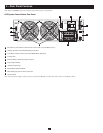
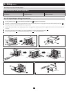
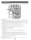
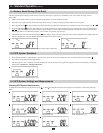
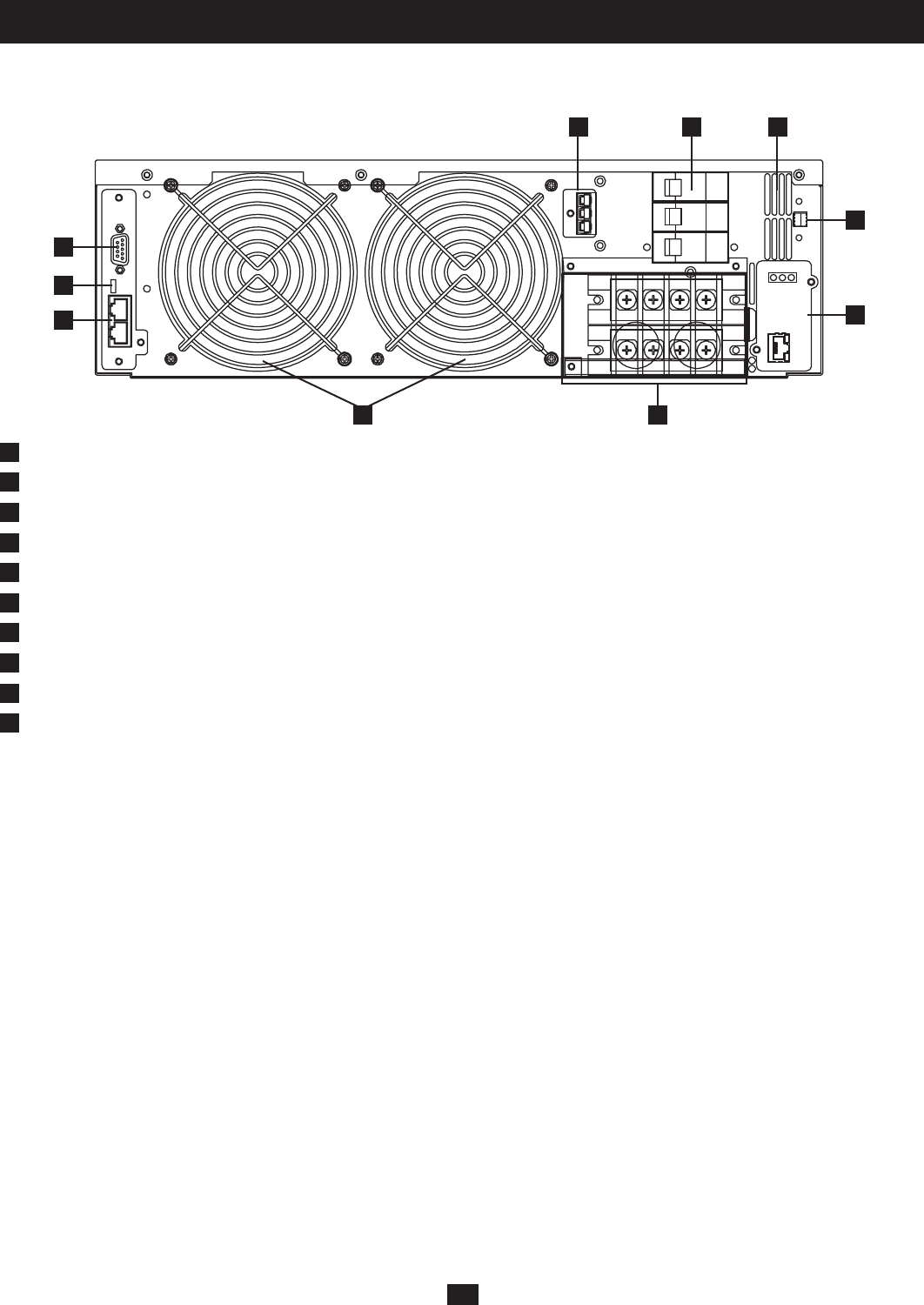
3 – Rear Panel Features
Note: Refer to Section 6-1 for a description of the UPS system’s control panel.
UPS System Power Module Rear Panel
A
RS-232Port(Note:RemovethenetworkcardinordertousetheRS-232port.)
B
Settings Switch for Parallel Redundancy Operation
C
CANBusConnectionPortsforParallelRedundancyOperation
D
Cooling Fans
E
ExternalBatteryPackDCCableConnector
F
UtilityInputBreaker
G
Ventilation Openings
H
Input/OutputTerminalBlock
I
EPO (Emergency Power Off) Connection
J
NetworkCard
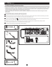
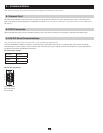
Note: One end of the Adapter Cable connects to the Power Module, and the other end connects to the Battery Pack.