


7
A
B
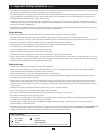
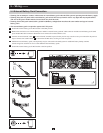
4-4 Mounting (Tower)
Warning: When mounting the UPS system in a tower position, make sure the control panel is closer to the top of the cabinet than the
bottom.
Note: The control panel can be rotated to match the UPS system’s position. Pull the panel out slightly, rotate it and push it back into place.
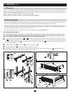
Tower Mounting Procedure
To mount the module in an upright, tower position, first determine the fitness of the hardware and procedures.
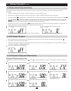
Use the optional two stands
A
and extensions
B
to tower mount the UPS’s power module, a battery module and a
second battery module (9U total).
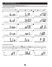
Adjustthefeettoawidthof10.25inches(26cm)foraUPSpowermoduleandbatterymodule,ortoawidthof
15.375inches(39cm)forthreeunits.Alignthefeetinyourinstallationarea,approximately10inches(26cm)apart.
Haveoneormoreassistantshelpyouplacetheunitsontheirsidesinthefeet.ThecontrolpaneloftheUPSshouldbe
the UPS’s upper corner and face outward.
4 – Mounting continued
5 – Wiring
DANGER! LETHAL HIGH VOLTAGE HAZARD!
All wiring should be performed by a qualified electrician, in accordance with the warnings in this manual and all applicable
electricalandsafetycodes.Incorrectwiringmaycauseseriouspersonalinjuryandpropertydamage.Read,studyand
understand the warnings listed in Section 2 – Important Safety Instructions before proceeding.
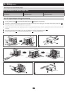
5-1 Wiring Preparation
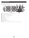
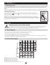
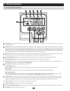
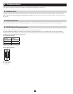
5-2 Terminal Block Diagram
• De-energizeallinputandoutput(ACandDC)oftheUPSsystemandexternalbatterypack.
• Markallcablesaccordingtotheircorrectpurpose,polarity,phaseanddiameter.
• ReviewthediagraminSection 5-2tofamiliarizeyourselfwiththeterminalblock.
• ConsultthetableinSection 5-3 to find the correct electrical input/output characteristics for the UPS system, including the required input/
outputcabling.(ACcablingisuser-supplied;DCcablingisincluded.)
R-S-T-N1: Terminals for AC utility input power.
G1: Terminal for UPS system input ground.
G2: Terminal for UPS system output ground.
L21-N22: Terminals for UPS system output.
Note: The maximum current for each terminal is 50 amperes.