


User’s Guide
Document #40181-120 Rev. A 1-4
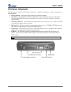
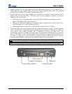
Print Server Components
The print server includes the following components. Detailed descriptions of these components are
provided below:
Power connector – The power supply cable plugs into this connector.
Test button – Pressing this button for less than three seconds will print a test page on the printer.
Pressing and holding this button for more than five seconds will reset the print server to factory
default settings.
LED status indicators – used to indicate the operational states of the print server. Refer to the LED
status light descriptions on the next page.
Ethernet Port – This port is used for connecting the print server to a 10/100Base-TX Ethernet card,
hub, router, or other wired access point for network access.
Parallel port – The parallel port is used for connecting the print server to the IEEE 1284-compliant
parallel port of your printer (parallel port models only).
USB port – The USB port is used for connecting the print server to the USB 2.0 port of your
printer. You must use a standard USB A (print server side) to B (printer side) cable (USB port
models only).
NOTE: A USB 2.0 cable must be used to take full advantage of the high-speed USB 2.0 connection.