2 Display Screens
2.1 Layout
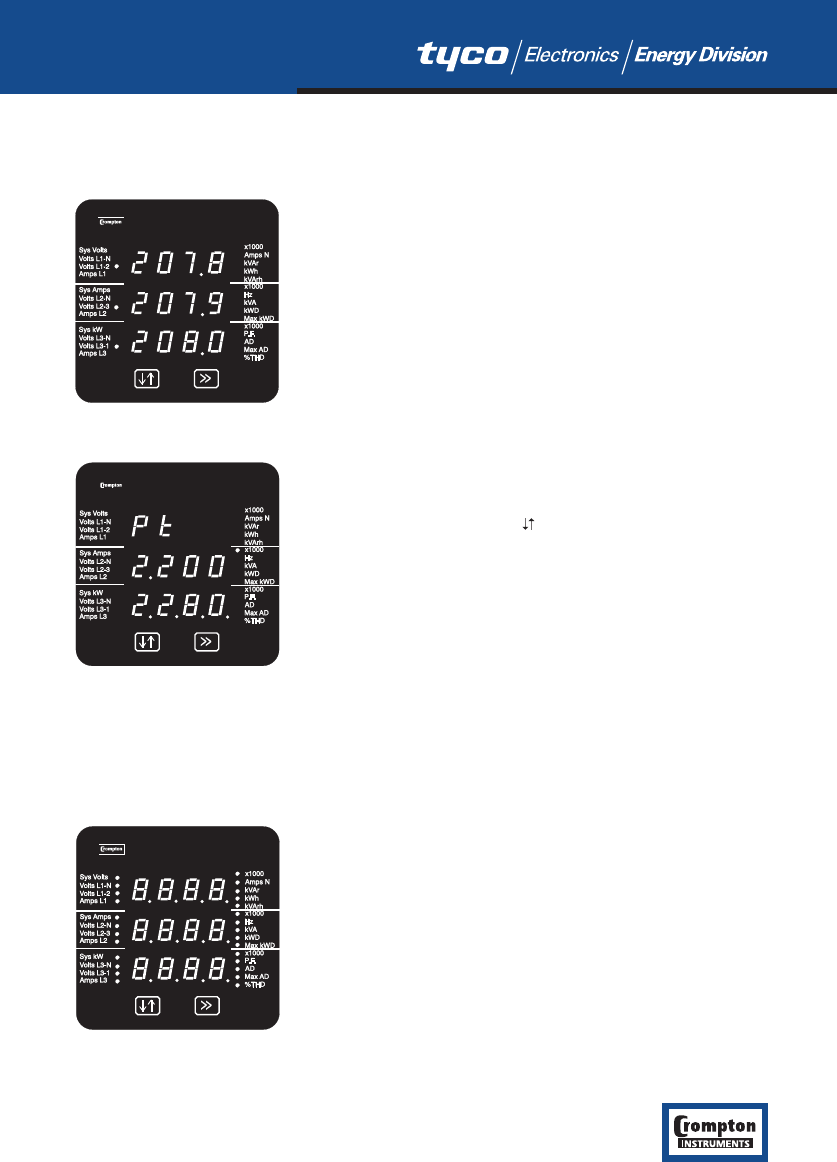
The screen is used in two main modes: display of measured
values and parameter setup.
In display mode, three measured values can be shown, one on
each row. For each row, the LED indicators show the parameter
being measured and the units.
The >> button moves between display screens.
In Set up mode, the top row shows an abbreviation of the
parameter name, the middle row shows the parameter value
being set and the bottom row is used for confirmation of the
entered value. In general, the key changes a parameter value
and the >> key confirms a value and moves on to the next
screen.
This example is the potential transformer primary voltage
confirmation screen.
The example screens shown in this manual are those relating to the 1540 models – the most
complex. The screens for simpler models are similar except that some of the parameters and
values are omitted. Section 1.1 shows the default display screens for the various models.
2.2 Start Up Screens
Initially, when power is applied to the Integra Display, two
screens will appear. The first screen lights the LED’s and can be
used as a display LED check.
11
Integra 1540, 1000, 0640, 0440, 0340, 0240 Issue 1 04/03
Voltage display
Setup confirmation screen


