59
Integra 1540, 1000, 0640, 0440, 0340, 0240 Issue 1 04/03
Modbus Holding Registers and Integra set up
Holding registers are used to store and display instrument configuration settings. All holding
registers not listed in the table below should be considered as reserved for manufacturer use
and no attempt should be made to modify their values.
The demand parameters may be viewed or changed using the Modbus protocol. Each parameter
is held in the 4X registers. Modbus Function Code 03 is used to read the parameter and Function
Code 16 is used to write.
Password Settings marked r/wp require the instrument password to have been entered into the
Password register before changes will be accepted. Once the instrument configuration has been
modified, the password should be written to the password register again to protect the
configuration from unauthorised or accidental change. Power cycling also restores protection.
Reading the Password register returns 1 if the instrument is unprotected and 0 if it is protected
from changes.
Demand Time is used to reset the demand period. A value of zero must be written to this
register to accomplish this. Writing any other value will cause an error to be returned. Reading
this register after instrument restart or resetting demand period gives the number of minutes of
demand data up to a maximum of the demand period setting. For example, with 15 minute
demand period, from reset the value will increment from zero every minute until it reaches 15.
It will remain at this value until a subsequent reset occurs.
Demand Period The value written must be one of the following 8,15, 20 or 30 (minutes),
otherwise an error will be returned.
System Type The System type address will display '1' for single phase 2 wire, '2' for 3 Phase 3
Wire, '3' for 3 Phase 4 Wire or 4 for single phase 3 wire.
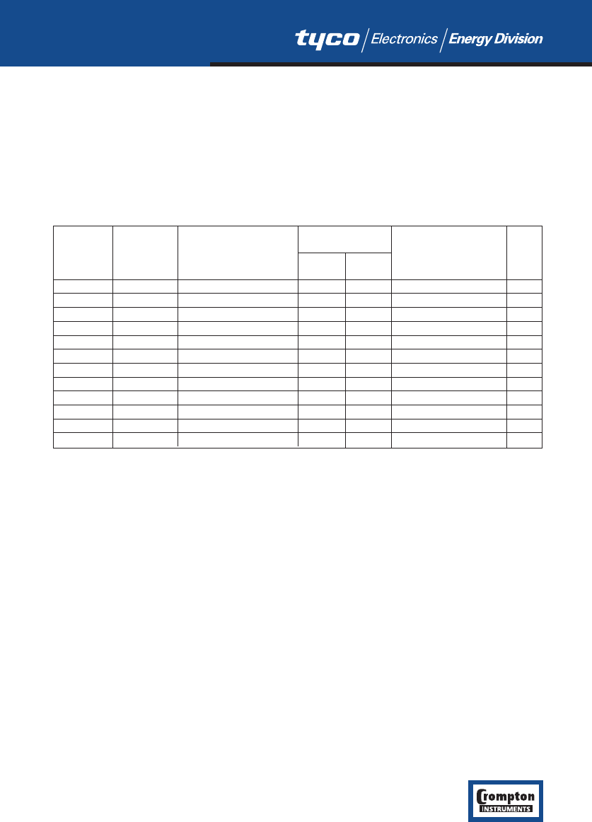
Register Parameter Parameter Modbus Start Valid range Mode
Number Address Hex
High Low
Byte Byte
40001 1 Demand Time 00 00 0 only r/w
40003 2 Demand Period 00 02 8,15,20,30 minutes. r/w
40007 4 System Voltage 00 06 1V - 400kV r/wp
40009 5 System Current 00 08 1-9999 A r/wp
40011 6 System Type 00 0A ro
40013 7 Relay Pulse Width 00 0C 3,5,10 (x20mS) r/w
40015 8 Energy Reset 00 0E 0 only wo
40023 12 Pulse Divisor 00 16 1,10,100,1000 r/w
40025 13 Password 00 18 0000-9999 r/w
40037 19 System Power 00 24 r/o
40041 21 Register Order 00 28 2141.0 only wo
40299 150 Secondary Volts 01 2A Min Vin-Max Vin r/wp
r/w = read/write r/wp = read and write with password clearance ro = read only wo = write only


