www.vxitech.com
CT-100C Introduction 15
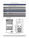
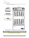
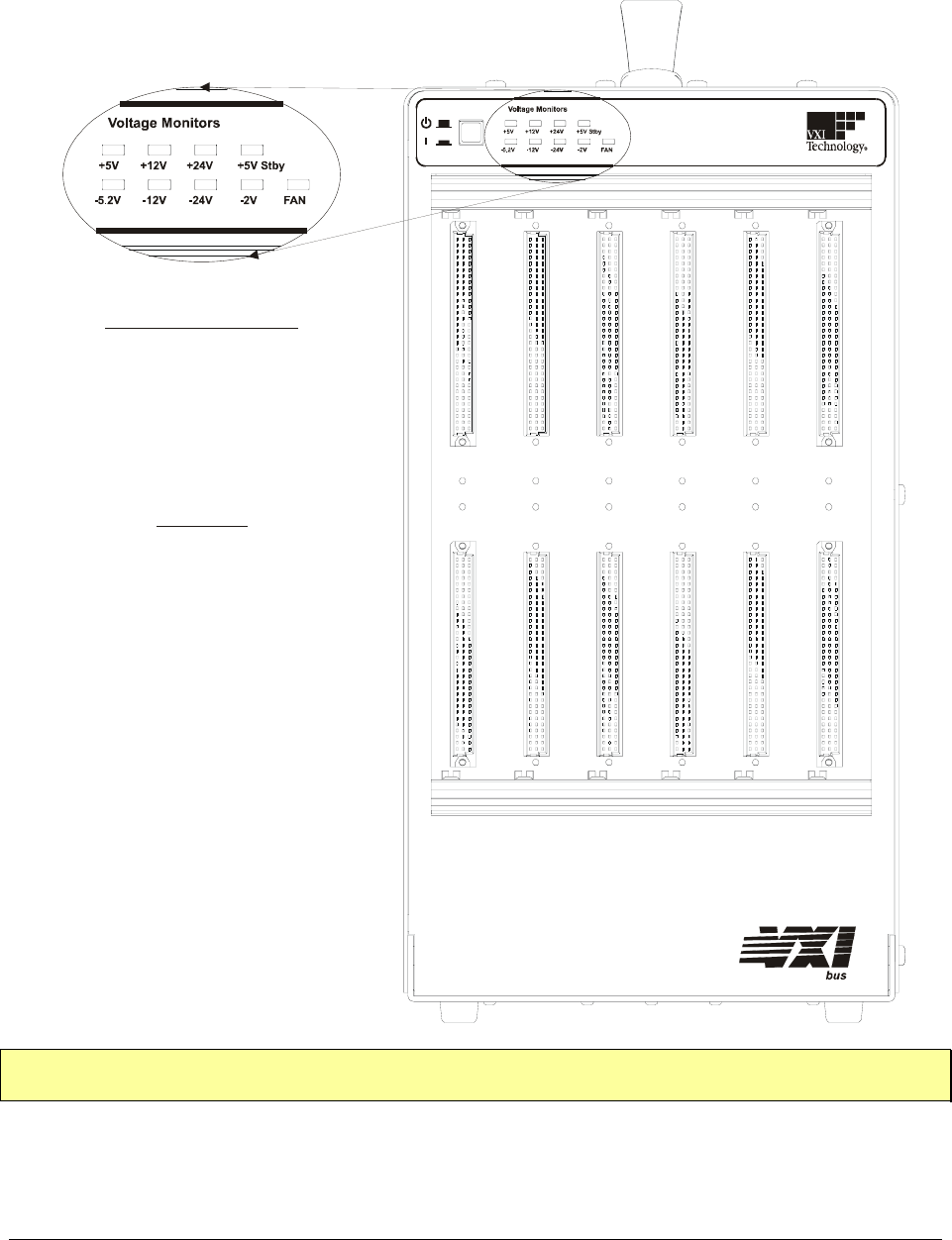
VOLTAGE MONITOR LEDS
The power supply lines are monitored and displayed on the front panel, providing information
pertaining to the chassis operational status.
0 1 2 3 4 5
V
oltage Monitors Power
+5V +12V +24V +5V Stby
-5.2V -12V -24V -2V FAN
CT-100C
VXI Mainframe
Voltage Monitor LEDs
Green : Within Voltage Specifications
: Under Voltage Specifications
: Over Voltage Specifications
Not Lit
Red
FAN LEDs
*Note: +5 V Stby is lit only when the +5 V is supplied by the
user to the + 5 V Stby pins (pins 8 & 12) of the monitor
connector located on the rear panel.
Green : Within Voltage Specifications
: Under Voltage Specifications
: Over Voltage Specifications
Not Lit
Red
NOTE At power up, the voltage monitor LED may blink for the first several seconds if the fan speed is
set to “HIGH”.
FIGURE 1-4: FRONT PANEL VOLTAGE MONITORS


