


TM-XR9B-01XN xiii
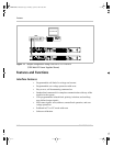
Figure 1-1 Sample configuration using Ethernet/RS-232 Interface
(1200 Watt DC Power Supplies Shown) - - - - - - - - - - - - - - - - - - - - 1–2
Figure 2-1 Power Supply Front Panel with Ethernet/RS-232 Interface Installed
(1200 Watt Power Supply Shown) - - - - - - - - - - - - - - - - - - - - - - - - 2–4
Figure 2-2 Ethernet/RS-232 Interface Subplate - - - - - - - - - - - - - - - - - - - - - - - 2–5
Figure 2-3 Ethernet/RS-232 Interface PCB - - - - - - - - - - - - - - - - - - - - - - - - - - 2–6
Figure 2-4 Removing the PCB- - - - - - - - - - - - - - - - - - - - - - - - - - - - - - - - - - - 2–8
Figure 2-5 RS-232 Connector Pinouts- - - - - - - - - - - - - - - - - - - - - - - - - - - - - 2–17
Figure 2-6 User Lines Signal Connector Circuit Block Diagram - - - - - - - - - - - 2–27
Figure 2-7 User Lines Cable with Ferrite Block - - - - - - - - - - - - - - - - - - - - - - 2–28
Figure 4-1 Voltage Calibration Setup - - - - - - - - - - - - - - - - - - - - - - - - - - - - - - 4–3
Figure 4-2 Current Calibration Setup - - - - - - - - - - - - - - - - - - - - - - - - - - - - - - 4–5
Figure B-1 Ethernet Bridge LEDs- - - - - - - - - - - - - - - - - - - - - - - - - - - - - - - - - B–5
Figures
TM-XR9B-01XN.book Page xiii Monday, April 19, 2004 9:00 AM