Operation
3–20 TM-XR9B-01XN
Troubleshooting
Diagnostic LEDs
This section describes the diagnostic LEDs found on the Ethernet/RS-232
Interface.
Computer Operating Properly (COP) LEDs
The Ethernet/RS-232 Interface provides three diagnostic LEDs, located at
CR167, CR166, and CR89 on its PCB. Refer to Figure 2-3, “Ethernet/RS-
232 Interface PCB” on page 2–6, for their locations. At present, these
LEDs turn on to signal COP events for the interface's microprocessors.
Issue a RST (reset) command to turn off the diagnostic LEDs.
The green COP LED at circuit designation CR167 indicates that the
Ethernet/RS-232 Interface microprocessor successfully recovered from a
timeout error due to a communications bus error. The event is transparent
to the RS-232 communications line which continues to function normally.
The red COP LED at CR166 indicates that a transparent restart caused by
noise in the master processor circuitry has occurred.
The red COP LED at CR89 indicates that a transparent restart caused by
noise in the slave processor circuitry has occurred.
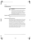
WARNING
Exercise caution when using and servicing power supplies.
High energy levels can be stored at the output voltage terminals
on all power supplies in normal operation. In addition,
potentially lethal voltages exist in the power circuit and the
output connector of power supplies which are rated at 40V and
over. Filter capacitors store potentially dangerous energy for
some time after power is removed.
TM-XR9B-01XN.book Page 20 Monday, April 19, 2004 9:00 AM


