


4
© 2001 Xantrex Technology Inc.
P/N 973-0012-01-02 Rev. A 05/01
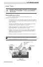
Surface Mounting
• Using the mounting bracket as a template, mark the positions for the
screw holes and an area where the cable(s) will feed through.
• Drill out the four screws holes (if required) and wire access opening.
Use a 3/16" bit if the supplied plastic anchors are used. If placing the
screws directly into the backing material, use a 3/32" bit. The wire
access hole should be at least 1/2" diameter to allow the connector to
pass through.
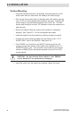
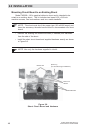
• Mount the bracket using the screws (and anchors if necessary)
supplied. See Figure 2-2. Do not overtighten the screws.
• Install the adaptor onto the bracket by pressing it tightly into place.
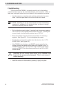
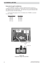
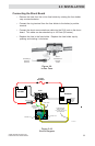
• Connect the communications cable (from the shunt) to the “J1 TO
SHUNT ONLY” jack on the TM500A. See Figure 2-3.
• If the TM500A is to function as an ON/OFF remote control for the
inverter, connect the remote control cable (not supplied) to the “J2
INVERTER ONLY” jack. This connector only functions if the inverter
contains a REMOTE jack that allows operation with an RC4 or RC8
remote control.
CAUTION: Do not reverse these cables or the TM500A
circuit board will be permanently damaged.
• Install the meter onto the adaptor by pressing it tightly into place.
2.0 INSTALLATION