


3
© 2001 Xantrex Technology Inc.
P/N 973-0012-01-02 Rev. A 05/01
Required Tools
• Phillips screw driver
• 3/32" and 3/16" drill bits
• Hole saw
If the TM500A will also function as a remote control (INVERTER ON/OFF),
an additional cable must be ordered. Available lengths are:
10 feet–TC/10 25 feet–TC/25
50 feet–TC/50 100 feet–TC/100
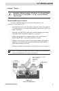
Pre-Installation
Before installing the TM500A, read all instructions and cautionary
markings located in this manual. The unit should be mounted in a clean, dry,
protected environment.
Determine the wire route to the batteries (and inverter, if the remote
INVERTER ON/OFF function is desired).
NOTE: Check for existing electrical, plumbing or other potential
areas of accidental damage prior to making cuts in structural
surfaces.
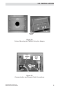
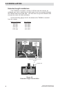
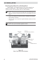
Mounting
The unit can be surface mounted (using the adaptor supplied) or flush
mounted into a rectangular opening. Provide at least one inch clearance
behind the meter circuit board for the cabling when flush mounting.
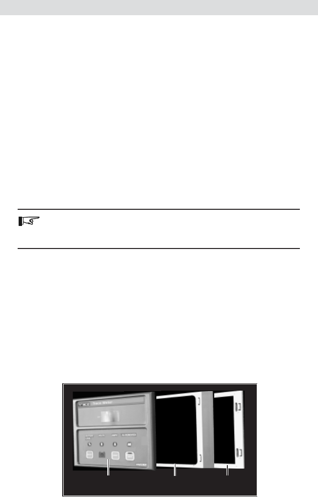
The TM500A ships in three sections:
• TM500A
• Adaptor for surface mounting
• Mounting Bracket
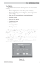
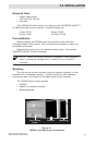
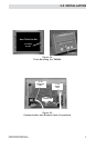
Figure 2-1
TM500A and Mounting Components
Trace Meter
Panel
Adaptor
Mounting
2.0 INSTALLATION