


6
© 2001 Xantrex Technology Inc.
P/N 973-0012-01-02 Rev. A 05/01
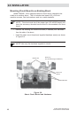
Flush Mounting
To flush mount the TM500A , an opening must be cut in the backing
material to allow room for the circuit board, wires and connectors. Allow at
least one inch depth behind the circuit board for the connectors and wires.
• Use the bracket as a template and mark the positions for the screw
holes. Mark the open area to be cut out for the circuit board.
NOTE: Carefully cut out the circuit board area from the backing
material (i.e., wallboard). Cut inside the lines so there is enough
area left to securely hold the screws.
• Drill out the four screw’s holes (if required) and wire access opening.
Use a 3/16" bit if the supplied plastic anchors are used. If placing the
screws directly into the backing material, use a 3/32" bit.
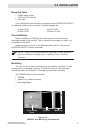
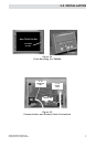
• Mount the bracket using the screws (and anchors if necessary)
supplied. See Figure 2-4. Do not overtighten the screws.
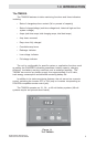
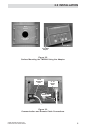
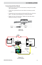
• Connect the communications cable (from the shunt) to the “J1 TO
SHUNT ONLY” jack (Figure 2-5).
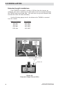
• If the TM500A is to function as an ON/OFF remote control for the
inverter, connect the remote control cable (not supplied) to the “J2
INVERTER ONLY” jack. This connector only functions if the inverter
contains a REMOTE jack that allows operation with an RC4 or RC8
remote control.
CAUTION: Do not reverse these cables or the TM500A circuit
board will be permanently damaged. This is not covered
under warranty.
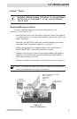
• Install the meter onto the bracket by pressing it tightly into place.
2.0 INSTALLATION