


Section 1. Features and Specifications
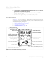
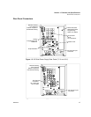
Rear Panel Connectors
16 Operating Manual for XPD Series Power Supply
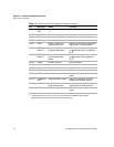
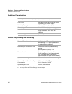
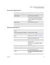
Table 1.2 Rear Panel J210 Connector Pins and Functions
Pin Reference Name Function
J210-1 TTL S/D
RTN
Shutdown Signal Return
(−)
Return for shutdown signal
1
.
J210-2 TTL S/D Shutdown Input (+) Input for shutdown signal.
1
J210-3 N/C No connection None.
J210-4 N/C No connection None.
J210-5 IPGM Output Current Limit
Programming Input
Input for current limit programming
signals from an analog device.
J210-6 VRMT
SELECT
Remote Output Voltage
Programming Select
Selects remote output voltage
programming when to jumpered to
pin 8.
2
J210-7 IRMT
SELECT
Remote Output Current
Limit Programming
Select
Selects remote output current limit
programming when jumpered to
pin 8.
2
J210-8 AGND Auxiliary Ground Auxiliary ground.
J210-9 N/C No connection None.
J210-10 N/C No connection None.
J210-11 N/C No connection None.
J210-12 IMON Output current monitor Output for output current monitor
signal.
J210-13 PGM/MON
RTN
Program/Monitor Return Return for voltage and current
program and monitor signals.
J210-14 VPGM Output Voltage
Programming Input
Input for voltage programming
signals from an analog device.
J210-15 VMON Output Voltage Monitor Output for output voltage monitor
signal.
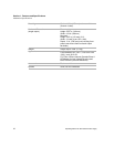
1. The TTL shutdown circuit is isolated to 500 V from the power supply output and chassis.
2. Jumpering pins J210-6, J210-7, and J210-8 will select both remote output voltage
programming and remote output current limit programming.