


Section 3. Local Operation
Using the Shutdown Function
Release A 39
Using the Shutdown Function
Use the shutdown function to disable or enable the supply’s output via a logic level
signal so that you can make adjustments to either the load or the power supply
without shutting off the power supply. Activate this function via remote control
through the rear panel J210 Programming and Monitoring connector, using a
transistor-transistor logic (TTL) or CMOS compatible signal. The input lines of the
shutdown circuit are optically isolated and will withstand a highpot test potential of
500 Vac maximum to chassis.
Controlling
Shutdown
Function via
J210
Connector
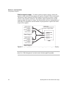
The shutdown circuit accepts a TTL or CMOS-compatible signal to disable or enable
the power supply output. Make connections for signals at the rear panel J210
connector. See “Rear Panel J210 Connector” on page 15, for more information about
the J210 connector.
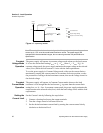
To activate the shutdown function:
• Connect the control signal source between J210 connector pin 2
(shutdown/positive) and pin 1 (shutdown return/negative).
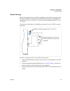
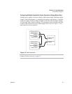
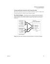
Master-Slave Tracking
For tracking positive and negative outputs, use the following setup:
1. Connect master return (J210 connector pin 13) to slave RTN (J210 connector pin
13).
2. Connect master Vmon (J210 connector pin 15) to slave voltage program input
(J210 connector pin 14).
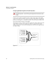
Note It is important to note that a Master-Slave configuration only applies to 2 positive
outputs, not split supply operation.
Note Master/slave power supplies must have the same output ratings.
As the slave is referenced to the master’s output, the noise and ripple on the slave may
increase. In addition, if the master’s output decreases due to the current limit acting,
the output voltage of the slave will follow. However, overcurrent of the slave supply and
consequent output voltage decrease will not reflect on the master.