Section 2. Installation
Remote Sensing
34 Operating Manual for XPD Series Power Supply
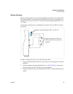
To compensate for losses in power leads connected to the output, your power supply
provides sense connections beside the output terminals. With remote sense leads in
place, the supply regulates to the displayed voltage at the point where the sense lines
are connected to the output leads (provided the sum of these lead losses does not
exceed 5 V per line or 3.5 V per line for a 7.5 V unit). With the sense lines
disconnected, the supply regulates the voltage at the output terminals.
Do not operate the supply with sense lines connected to the load without also
connecting the load power leads to the output terminals. Avoid reversing positive and
negative lead connections.
Sense Wiring
Note Long load leads with large capacitance at the load and remote sensing can cause
voltage instability due to inductance of the load leads. Measures to reduce inductance
and/or capacitance (raising resonant frequency) or using local sense can be beneficial
in stabilizing the system.
WARNING
There is a potential shock hazard at the sense connectors when using a power
supply with a rated output greater than 40 V. Select wiring with a minimum
insulation rating equivalent to the maximum output voltage of the power supply
for use as local sense jumpers or for remote sense wires. Ensure that
connections at the load end are shielded to prevent contact with hazardous
voltages.


