Section 2. Installation
Load Connection
32 Operating Manual for XPD Series Power Supply
Inductive
Loads
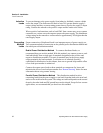
To prevent damage to the power supply from inductive kickback, connect a diode
across the output. The diode must be rated at least 20% greater than the supply’s
output voltage and have a current rating greater than or equal to the supply’s output
rating. Connect the cathode to the positive output and the anode to the return.
Where positive load transients such as back EMF from a motor may occur, connect
a transorb or a varistor across the output to protect the power supply. The breakdown
voltage rating for the transorb or varistor must be approximately 10% higher than the
rated supply output.
Connecting
Multiple
Loads
Proper connection of distributed loads is an important aspect of power supply use.
Two common methods of connection are the parallel power distribution method and
the radial power distribution method.
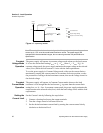
Radial Power Distribution Method To connect distributed loads, we
recommend that you use this method. With this method, you connect power to each
load individually from a single pair of terminals designated as the positive and
negative distribution terminals. This pair of terminals may be the power supply
output terminals, the load terminals, or a distinct set of terminals specially
established for distribution. In this scheme, there are no ground loops and the effect
of one load upon another is minimized.
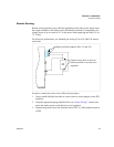
Connect the remote sense leads to these terminals to compensate for losses and
minimize the effect of one load upon another. See “Remote Sensing” below for more
information about using remote sensing.
Parallel Power Distribution Method This distribution method involves
connecting leads from the power supply to one load, from that load to the next load,
and so on for each load in the system. The voltage at each load depends on the current
drawn by the other loads and DC ground loops are developed. Except for low-current
applications, we recommend that you do not use this method.


