


GSA Operations
Document Number: 401-364
17
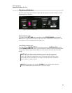
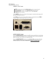
CAMERA / COM 1 Switch
NOTE: In either position, the CAMERA/COM1 switch only works when the
NONSECURE/STU switch is in the NONSECURE position. When the
NONSECURE/STU switch is in the STU position, both COM1 and
CAMERA ports are disabled.
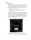
In the CAMERA position, the serial port of the computer is connected to the orange serial
port on the inside panel of the case.
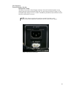
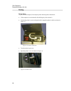
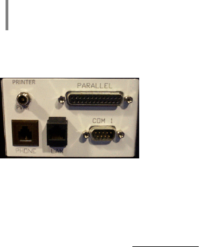
In the COM 1 position, the serial port of the computer is connected to the 9-pin COM 1
connector (DB9) on the back panel of the case (see Figure 7).
Figure 7 External COM
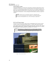
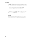
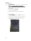
NONSECURE/STU Switch
When the NONSECURE/STU switch is in the STU position (the LED in the switch lights
up red), all data passes through the STU-III. In this position, the STU-III can be used in all
modes: Non-Secure Voice, Secure Voice, and Secure Data.
When the NONSECURE/STU switch is in the NONSECURE position (the LED in the
switch is not lit up), all non-secure communication connections (LAN and COM1) are
connected. Data sent or received in this mode will be only in Non-Secure mode.