


GSA Operations
Document Number: 401-364
5
Table of Figures
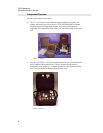
Figure 1 "A" Case .........................................................................................................8
Figure 2 "B" Case .........................................................................................................8
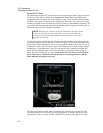
Figure 3 External A/C Power Input .............................................................................10
Figure 4 External D/C Power Input .............................................................................11
Figure 5 Power Inverter Panel ....................................................................................12
Figure 6 Controls and Indicators.................................................................................15
Figure 7 External COM ...............................................................................................17
Figure 8 Power Switch and Indicator..........................................................................18
Figure 9 Logging in .....................................................................................................19
Figure 10 Shut Down Windows ..................................................................................20
Figure 11 Creating a New Document. ........................................................................22
Figure 12 Retrieving an Existing Document ...............................................................23
Figure 13 Printer connection.......................................................................................24
Figure 14 Printer cover ...............................................................................................24
Figure 15 Printer cartridge ..........................................................................................25
Figure 16 PageScan Scanner.....................................................................................28
Figure 17 Foto Touch..................................................................................................29
Figure 18 OCR Scan...................................................................................................30
Figure 19 Telephone Connection ...............................................................................31
Figure 20 LAN/Modem Connections...........................................................................31
Figure 21 Welcome Message .....................................................................................33
Figure 22 New Connection Setup...............................................................................34
Figure 23 Phone Number ...........................................................................................35
Figure 24 ProComm Plus Indicators...........................................................................37
Figure 25 ProComm Send File ...................................................................................38
Figure 26 ProComm Receive Screen.........................................................................39
Figure 27 Selecting the ProComm Plus Printer..........................................................40