


PAGE 21
206-3634
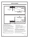
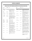
SYSTEM ALIGNMENT
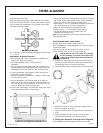
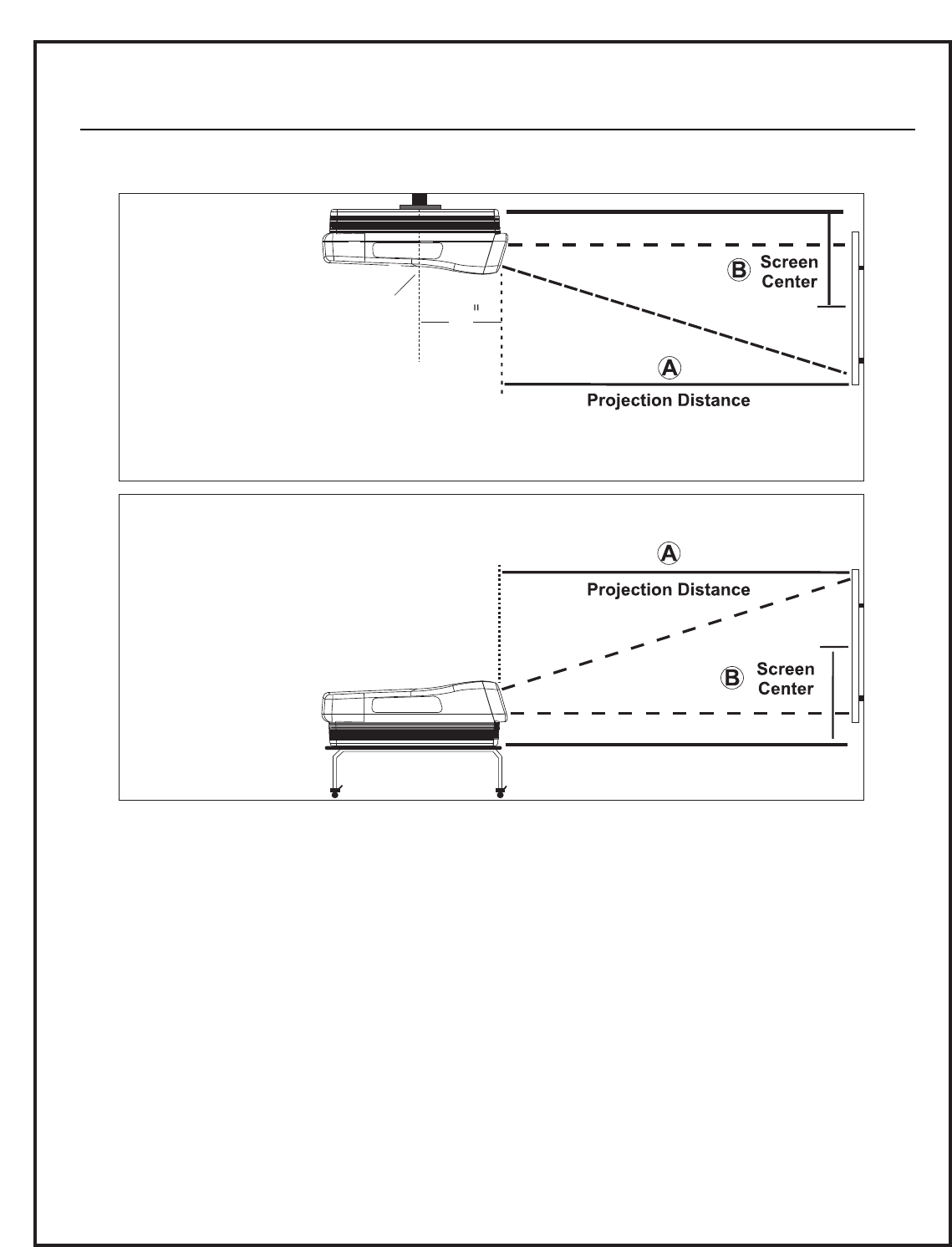
Mount Bracket Center
11" from Front Panel
Under the Green CRT
Center
11
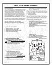
III. PRELIMINARY ALIGNMENT SETUP
The following procedures are intended for complete
“Geometry/Convergence” setup. Use the customer’s signal for
doing phase, and size adjustments. You can use the internal
patterns for shape and convergence if the customer signal
sources do not have a cross-hatch pattern.
If you are realigning a single CRT, due to replacement, or doing
alignment touch up, perform the following steps as needed.
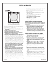
1. Yoke Tilt Alignment
Use a cross-hair or cross-hatch pattern. Monitor only the cen-
ter- most horizontal line of the pattern to check yoke tilt.
Do not use SW9501, on the 9-1510 module, to disable conver-
gence. The vertical circuit is not disabled, only the horizontal is
disabled.
a. Set Horizontal DC centering to “0” (red, green, blue).
b. Set Vertical DC centering:
Floor: Red = -30; Green = -20; Blue = -30.
Ceiling : Red = 30; Green = 20; Blue = 30.
c. In geometry mode and convergence mode (green, red, and
blue) set “SKEW” H = 0 and “SKEW” V = 0.
d. Adjust the Red, Green, and Blue yokes for no horizontal
tilt or twist.
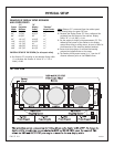
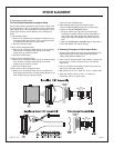
2. Yoke Ring Magnet and Astigmatator Alignment
Verify Only - This is not a normal field adjustment.
The astigmatator assembly should be mounted 62.5 mm from
the video output module (from the front edge of the video out-
put module to the six pole rings). Refer to figure on page 24.
Astigmatator Alignment Verification Test
Adjust for the best electrical and mechanical focus.
Continued on next page
Text continued from page 18