PAGE 25
206-3634
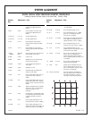
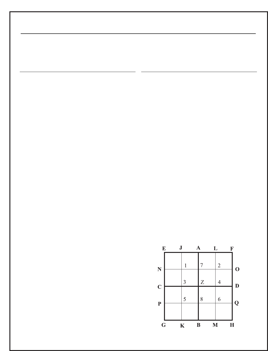
SYSTEM ALIGNMENT
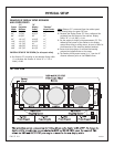
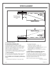
1. SIZE H. Size Set to fill screen at C and D. (Use
external source not internal test
pattern)
2. SIZE V. Size Set to fill Screen at A and B. (Use
external source not internal test
pattern.)
3. LIN TB LR H. Lin L-R Set equal widths CZ=ZD
4. LIN TB LR V. Lin T-B Set equal height AZ=ZB
5. LIN C H. Lin C Set box width at center equal to
average of left and right box widths
and size.
6. LIN C V. Lin C Set box heights at center equal to
average of top and bottom box widths
and size.
7. SMALL H&V Video Set the position of the external source
ARROWS Phase to be centered on the screen.
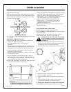
8. SKEW V. Skew Level line C-D.
9. BOW Bow V. Straighten line C-D (note that some
screen frames are curved).
10. SKEW H. Skew Line A-B edges equal distance to
screen edge.
11. BOW H. Bow Straighten Line A-B
12. KEY V. Key Set bottom edge G-H straight with
respect to screen border.
13. PIN V. Pin Set for straight bottom edge, line G-H
(corners G & H move, center B is
stable.)
14. S-ING V. ‘S’ Set for straight bottom edge, line G-H
(middle areas K & M move in opposite
direction, center B; and ends G & H are
stable).
15. W-M V. W-M Adjust for straightest line G-H (middle
areas K & M move in same direction,
center B and ends G & H are
stationary).
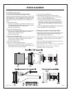
16. KEY H. Key Set right edge F-H straight with respect
to screen border (top and bottom move
in opposite directions; center D is
stable.)
17. PIN H. Pin Set for straight right edge, line F-H
(corner F&H move, center D is stable.)
18. S-ING H. ‘S’ Set for straight right edge, line F-H
(middle areas O & Q move opposite and
center D and ends F & H are stable.)
19. T/L KEY V. Top Key Set top edge E-F straight with respect
to screen border.
20. T/L PIN V. Top Pin Set for straight top edge, line E-F.
21. T/L S V. Left S Set for straight edge, line E-F (middle
areas J & L move opposite; center A
and ends E & F are stable).
22. T/L KEY H. Left Key Set left edge E-G straight with respect to
screen border top and bottom move in
opposite directions, center C is stable).
23. T/L PIN H. Left Pin Set for straight left edge, line E-G
(corners E & G move, center C is stable).
24. T/L S H. Left S Set for straight left edge, line E-G
(middle areas N & P move opposite; center
C and ends E & G are stable).
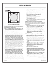
25. IN-KEY H. In Key Set J-K and L-M straight with respect to
line E-G, A-B, and F-H (adjust for
minimal internal keystone; top bottom
move in opposite directions; centers 3 and
4 are stable).
26. IN-PIN H. In Pin Set J-K and L-M straight (adjust for
minimal internal pincushion).
27. W-MV W-M Average error for straightest lines G-H
and E-F (middle areas K & M, and J & L
move in same direction; center B, A and
ends G & H, are stationary).
28. Touch up all controls Due to the interaction of IN-XXX con-
trols, key controls, and pin controls for
best overall convergence, it may be
necessary to ‘tweak’ the other controls.
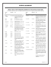
DIGITAL DISPLAY SETUP PROCEDURE GEOMETRY CONVERGENCE
Geometry controls all three colors at the same time. January 1998
Remote Adjustment Goal Remote Adjustment Goal
Key Key


