


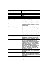
21
Signal
Quality
SNR
Green ON: The PER is less than 8%
OFF: The PER is larger than 8%
LAN
LAN 10M
LAN
100M
Green
Orange
ON: The LAN 10/100M connection is established Flash: The
LAN 10/100M interface is transmitting/receiving
OFF: The LAN 10/100M connection is not ready
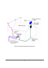
5.8. System LED Indication
For easily configuring A-6000 system status, we reserve system LED in IDU to indicate whether system run
in ok state or in failed state. If system LED is green light, that means system ok; if system LED flash with
red/green light, it means system is disconnected; once in red light, it means A-6000 with some system errors
there. There are some events to lead system LED into red light mode; and events are listed as following:
ODU/IDU connection fails.
END devices Init Fail.
BU init fails.
Memory Allocate Descriptor error.
H/W Allocate Descriptor error.
BU Trap Monitor Task.
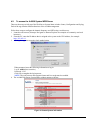
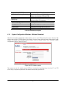
5.9. RSSI LED Indication
For easily configuring A-6000 radio status, 3 RSSI LED are designed in IDU to indicate radio RSSI status.
Thefollowing mapping table explains the meaning of RSSI – “L”, “M”, and “H” LED signal status.
RSSI (dBm) L M H
<= –65 Off Off Off
-65<RSSI<=-60 Flash Off Off
-60<RSSI<=-55 On Off Off
-55<RSSI<=-50 On Flash Off
-50<RSSI<=-45 On On Off
-45<RSSI<=-40 On On Flash
RSSI>-40 On On On
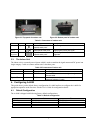
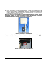
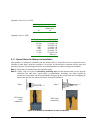
5.10. Alignment Tools
While easily adjusting directional antenna, we design alignment tools to indicate radio signal strong or not. In
alignment tools, we use Level to display current RSSI status and design beep in different frequency to
represent different SNR value. Following two tables are Alignment Tools Level value mapping with RSSI,
and Alignment Tools vs. SNR mapping table, respectively.