


2
List of figures
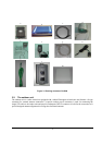
Figure 3-1 Packing contents of A-6000 ................................................................................ 6
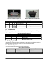
Figure 3-2 Top panel of outdoor unit .................................................................................... 7
Figure 3-3 Bottom panel of outdoor unit ............................................................................. 7
Figure 4-1 Status-System information.................................................................................. 8
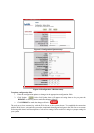
Figure 4-2 Status Wireless information................................................................................ 9
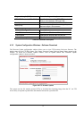
Figure 4-3 Configuration-System setup............................................................................. 10
Figure 4-4 Configuration –Wireless setup......................................................................... 10
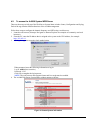
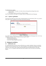
Figure 4-5 FTP firmware update ........................................................................................... 12
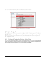
Figure 4-6 System log ............................................................................................................. 13
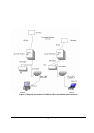
Figure 5-1 Physical connection of A-6000 for office test with flat panel antennas 14
Figure 5-2 Physical Installation of A-6000 with flat panel antenna............................. 15
Figure 5-3 Mounting Bracket Assembly............................................................................. 16
Figure 5-4 Attach the Mounting Bracket to Outdoor Unit.............................................. 16
Figure 5-5 Install Outdoor Unit to the Mast ....................................................................... 16
Figure 5-5 Install Antenna to the Outdoor Unit ................................................................ 17
Figure 5-6 Connect Cat-5 cable to the outdoor unit ....................................................... 17
Figure 5-8 Connect Grounding wire to the outdoor unit ............................................... 18
Figure 5-9 Cable Connections of Network/Power Injector............................................ 19
Figure 5-10 Waterproof installation of cable connections ............................................ 22