


7
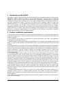
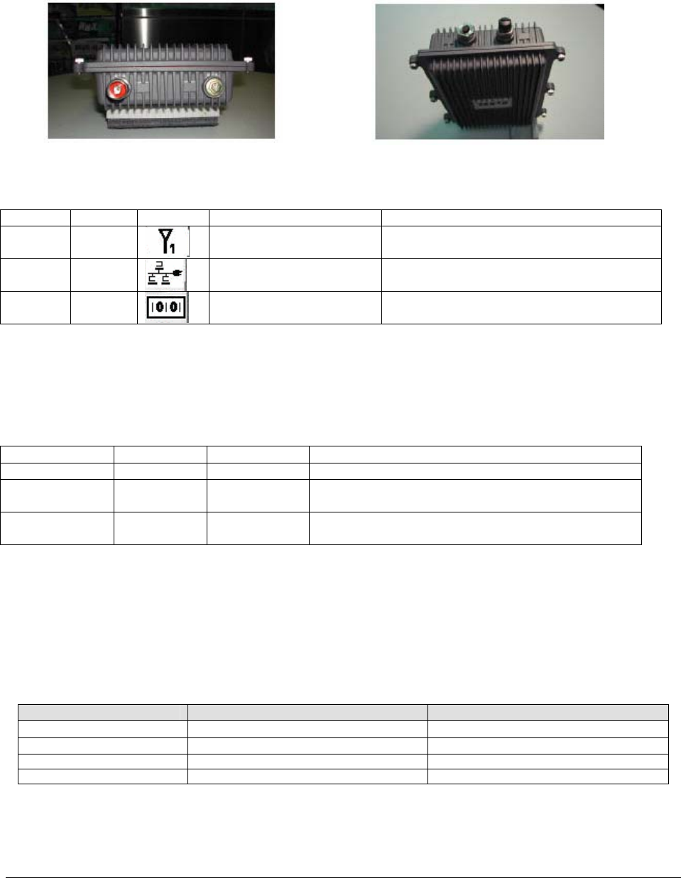
Figure 3-2 Top panel of outdoor unit
Figure 3-3 Bottom panel of outdoor unit
Table 3-1 Connectors of outdoor unit
Function Location Label Interface Description
Antenna Top
N male RF connector with
special water proof
Connecting to the outdoor antenna
Signal &
Power
Bottom
8-pin female connector
with special water proof
Connecting to the indoor interface unit
supplying the power and signal
Antenna
alignment
Bottom
8-pin male connector with
special water proof
Connecting to AK-100 for antenna
alignment
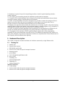
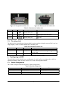
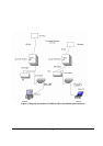
3.3. The Indoor Unit
The indoor unit is a network/power injector which is used to combine the signal stream and DC power into
single category-5 cable to connect outdoor unit. It has three ports.
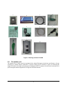
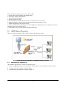
Table 3-2 Connectors of indoor unit
Function Name Connector Description
Power
POWER
Power jack Connecting to the outdoor antenna
Ethernet
TO LAN
RJ45 User for CPE connection via straight through
Ethernet cable
Signal & Power
TO RADIO
RJ45 Used for outdoor unit connection via special
waterproof category-5 cable
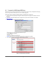
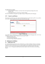
4. Configuring A-6000
This guide shows you the default factory configuration of A-6000 and how to configure the A-6000 for
appropriate operation at the first time. See the User’s Guide for configuration details.
4.1. Default Configuration
The A-6000 is shipped with following factory default configurations:
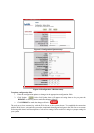
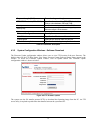
Table 4-1 Default configuration
BU RU
LAN IP 192.168.1.1 192.168.1.1
Subnet Mask 255.255.255.0 255.255.255.0
Wireless ESSID Wireless Wireless
Username/Password admin/1234 admin/1234