


Chapter 45 PoE Commands
Ethernet Switch CLI Reference Guide
172
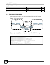
45.2 Command Examples
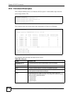
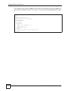
This example enables Power over Ethernet (PoE) on ports 1-4 and enables traps when the
power usage reaches 25%.
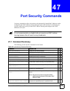
This example shows the current status and configuration of Power over Ethernet.
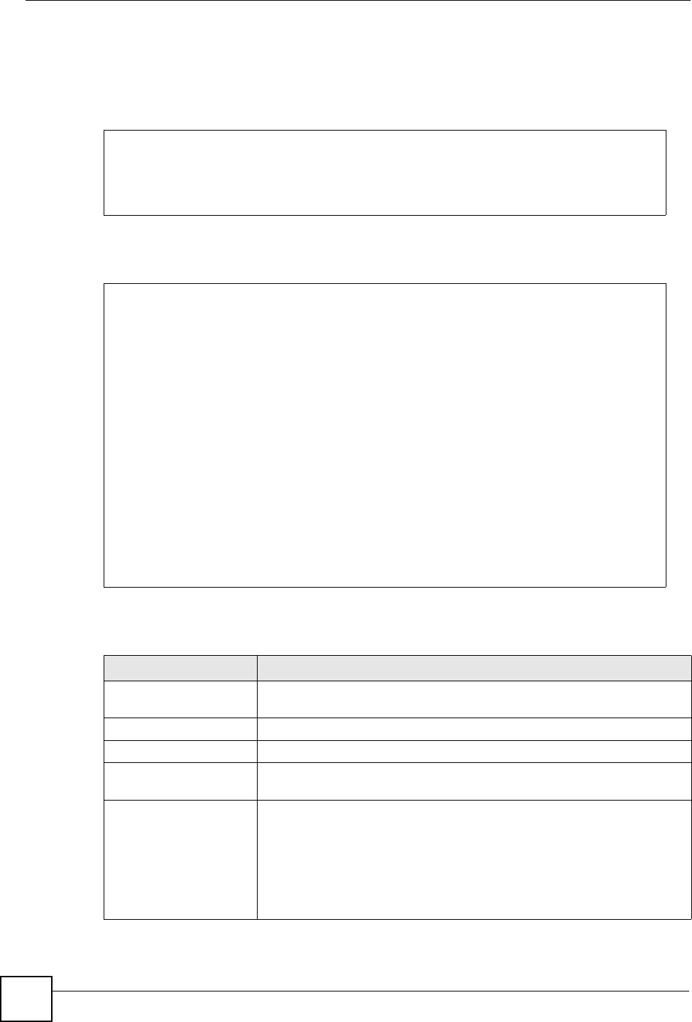
The following table describes the labels in this screen.
sysname# configure
sysname(config)# pwr interface 1-4
sysname(config)# pwr usagethreshold 25
sysname(config)# pwr mibtrap
sysname(config)# exit
sysname# show pwr
Averaged Junction Temperature: 35 (c), 95 (f).
Port State PD Class Priority Consumption (mW) MaxPower(mW)
---- ------- --- ----- -------- ---------------- ------------
1 Disable off 0 Critical 0 0
2 Enable off 0 Critical 0 0
3 Enable off 0 Critical 0 0
4 Enable off 0 Critical 0 0
5 Enable off 0 Critical 0 0
6 Enable off 0 Critical 0 0
7 Enable off 0 Critical 0 0
--------------------------------- SNIP ---------------------------------
Total Power:185.0(W)
Consuming Power:0.0(W)
Allocated Power:0.0(W)
Remaining Power:185.0(W)
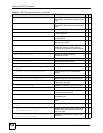
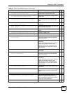
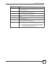
Table 100 show pwr
LABEL DESCRIPTION
Averaged Junction
Temperature
This field displays the internal temperature of the PoE chipset.
Port This field displays the port number.
State This field indicates whether or not PoE is enabled on this port.
PD This field indicates whether or not a powered device (PD) is allowed to
receive power from the Switch on this port.
Class This field displays the maximum power level at the input of the PoE-
enabled devices connected to this port. The range of the maximum power
used by the PD is described below.
0: 0.44~12.95 W
1: 0.44~3.84 W
2: 3.84~6.49 W
3: 6.49~12.95 W