Page 14
MSL600
Installation, Operation & Maintenance Manual
IP262/Z0, Rev. AB
February 2012
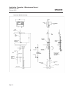
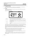
3.4 Transducer connections
The MSL600 is housed in an ABS enclosure rated to IP66. The lower section of the housing is for cable
connections and the upper part has the LCD and keypad controls.
It is not necessary, or advisable, to remove the lid of the upper part of the enclosure. There are no user
serviceable parts inside.
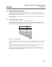
All field wiring connections are accessible by removing the lower lid, which is secured by four screws. Inside the
terminal area, all connections are made using screw terminals. All terminal blocks are suitable for wires 0.5mm
2
to
2.5mm
2
(26 to 12 AWG). Insulation should be stripped back 7.0mm (0.25 inches).
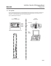
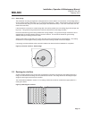
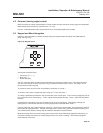
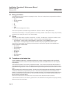
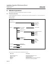
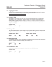
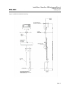
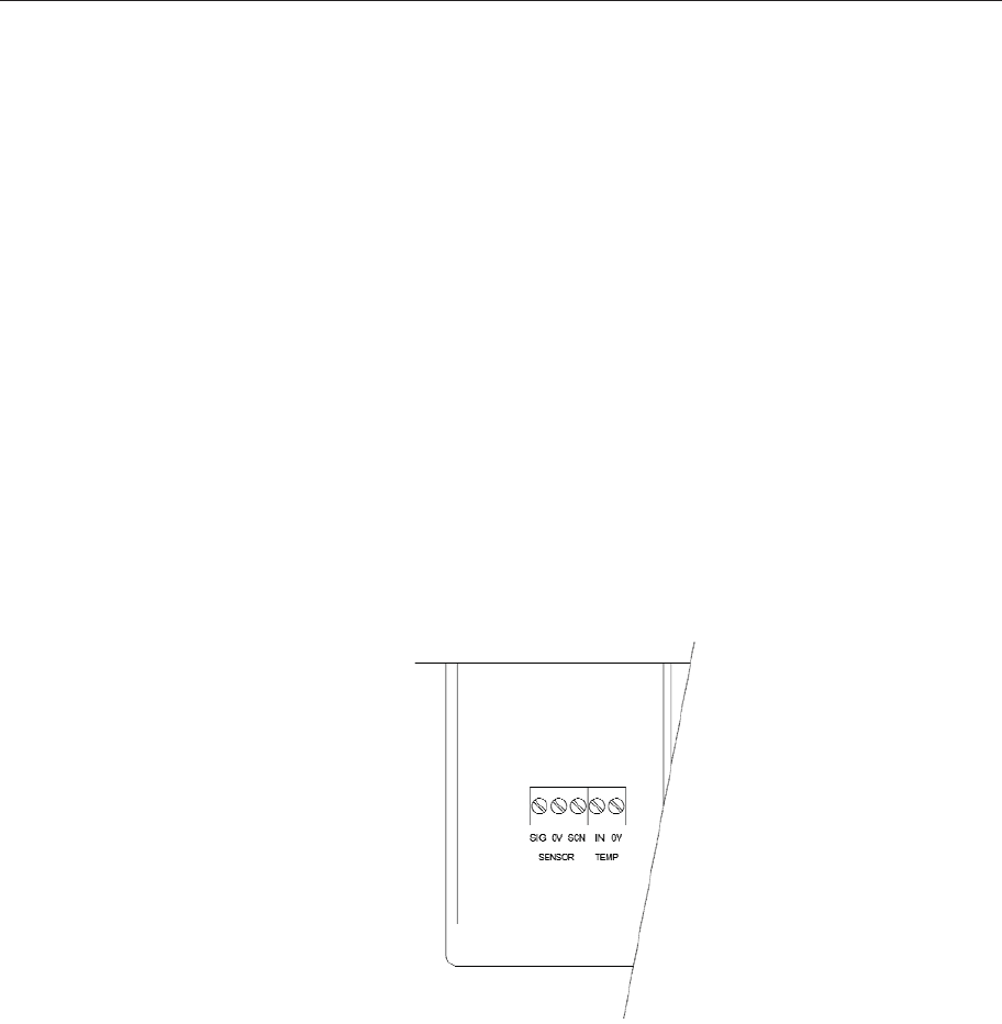
The transducer cable comprises of five wires, see Figure (6), the connections for which are as follows:
• White wire - Transducer signal wire. This should be connected to the terminal
block marked ‘SENSOR’ and ‘SIG’.
• Black wire - Transducer 0V wire. This should be connected to the terminal block
marked ‘SENSOR’ and ‘0V’.
• Yellow wire - Transducer screen wire. This should be connected to the terminal
block marked ‘SENSOR’ and ‘SCN’.
• Red wire - Temperature compensation positive wire. This should be connected
to the terminal block marked ‘TEMP’ and ‘IN’
• Brown wire - Temperature compensation 0V wire. This should be connected to
the terminal block marked ‘TEMP’ and ‘0V’.
Figure (6): Transducer cable wiring
All connections to the transducer are intended to be made via the first M20 cable gland (fitted) on the left-hand
side, at the bottom of the MSL600 enclosure.
3.5 Power and other electrical connections
(See also section (i), safety precautions)
It is the responsibility of the installer to observe all local regulations and approval requirements, and to use cable
to suit the environmental requirements of the particular application.
Prior to applying power to the unit ensure that the two voltage selection switches are set to the appropriate
voltage for the installation.
In the event of a fuse needing replacement the user must ensure that the mains input fuse (F1) has a rating of
200mA (F) and the cleaning compressor (F2) has a rating of 1A(T).