Page 15
MSL600
Installation, Operation & Maintenance Manual
IP262/Z0, Rev. AB
February 2012
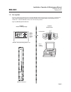
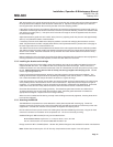
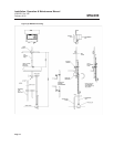
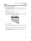
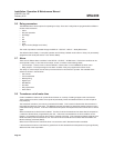
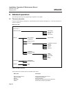
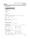
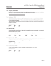
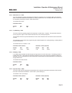
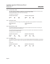
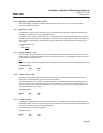
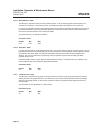
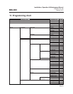
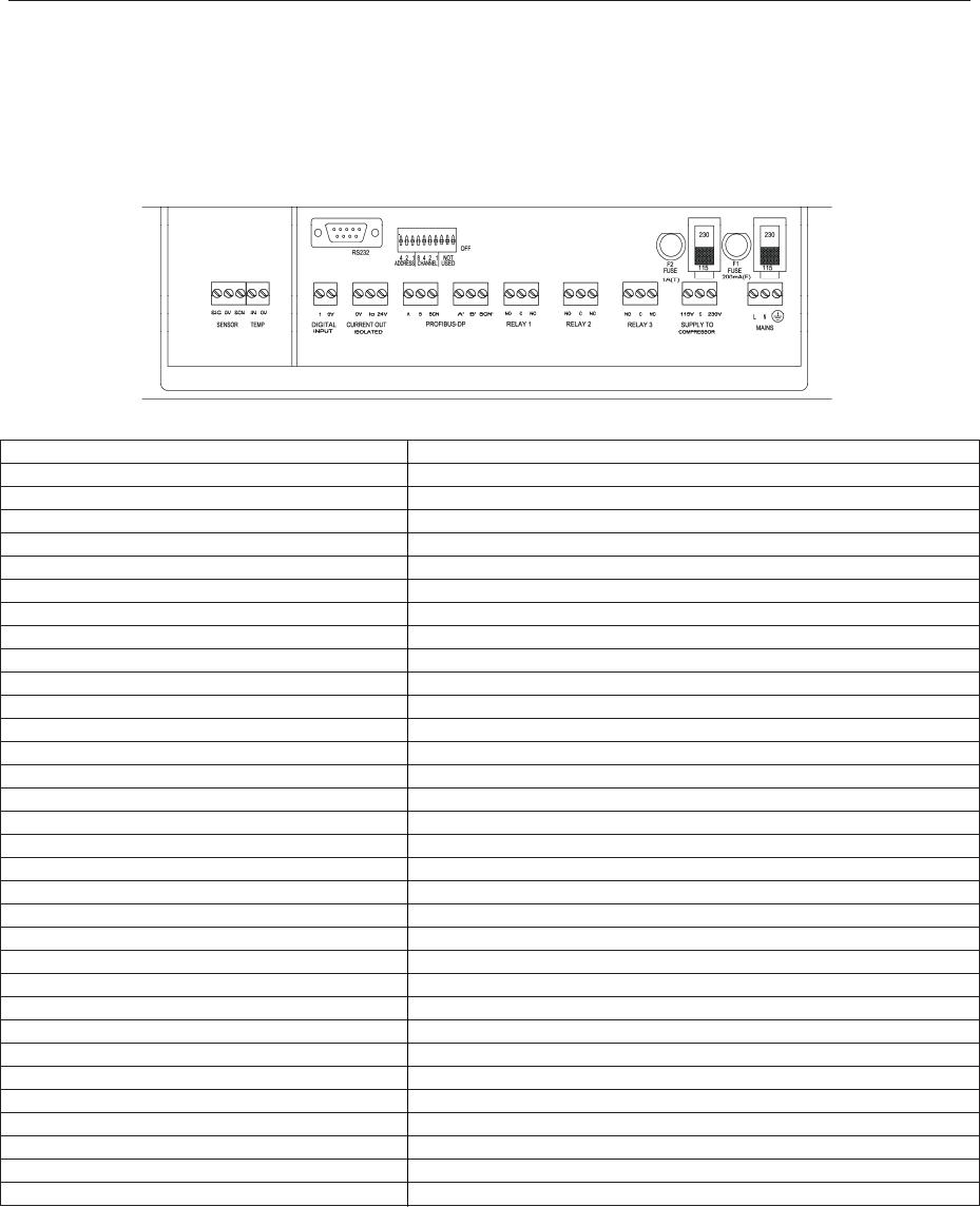
The diagram below, Figure (7) shows the layout of external connection terminals of the MSL600 with the lower
terminal housing cover removed. Table (A) gives a description of each.
Note:
When wiring of the unit is finished, ensure that the terminal housing cover is replaced the correct way up, i.e. with
the bevelled edge uppermost otherwise the IP rating of the enclosure may be compromised.
Figure (7): External connection terminals
SENSOR TEMP (see note 1)
SIG Transducer sonar signal (white)
0V Transducer zero volts (black)
SCN Transducer screen (yellow)
IN Temperature compensation signal (red)
0V Temperature zero volts (brown)
DIGITAL INPUT (see note 2)
1 Digital input signal
0V Digital input zero volts
CURRENT OUT ISOLATED
0V Current output zero
Io Current out
24V 24V source for current output (Not normally used)
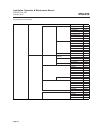
RELAY 1 (de-energised state)
NO Normally open
C Common
NC Normally closed
RELAY 2 (de-energised state)
NO Normally open
C Common
NC Normally closed
RELAY 3 (de-energised state)
NO Normally open
C Common
NC Normally closed
COMPRESSOR (Factory wired)
115V (White) 115V supply for the cleaning compressor
C (Purple) Common for the cleaning compressor
230V (Orange) 230V supply for the cleaning compressor
MAINS
L Live terminal for mains supply
N Neutral terminal for mains supply
E Earth terminal for mains supply
Table (A): Connection descriptions reading from left to right (all via M20 cable glands)