


16 C
HAPTER
1: W
EB
M
ANAGEMENT
O
VERVIEW
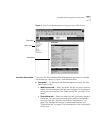
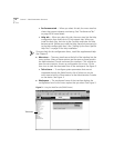
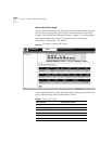
About the Device Image
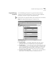
As you move your pointer over the image, a blue border outlines the part
of the device image under your pointer.
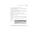
Click an element in the device
image in the DeviceView workspace (shown in Figure 5), a configuration
form appears below the image. See Figure 6 and “Configuring
Parameters in DeviceView” for details.
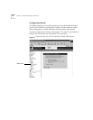
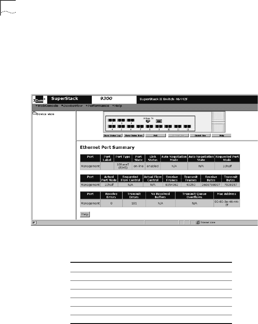
Figure 6
DeviceView Image (9300 Shown)
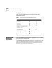
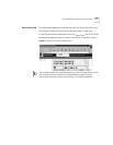
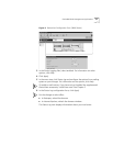
As you view the device image, the current state of the system and of each
port is indicated by a color, as described in Table 4.
Table 4
Status Color Codes
Color/Shade Indicates this status
Green Enabled, link present
Partial Shading (dark edge) Disabled, link present
Black Enabled, link absent
Gray Shading Disabled, link absent
Red Partitioned, link present
Yellow Resilient, link absent