


Designing and Expanding the Network 2 - 13
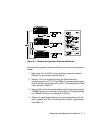
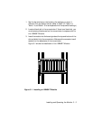
To set redundancy between two 10BASE-T Modules, connect two links
between the modules. The redundant link must be connected to a port on
the same 10BASE-T Module as the primary link. Use a crossover adapter
between each link unless you choose to uncross port 8 on one of the
modules to make the connection. Refer to Chapter 1 for information on
using crossover mode. Then use the SET PORT <slot.port> MODE
REDUNDANT <slot.port> command to specify which port is the primary link
and which is the backup link.
Note: If the 10BASE-T Modules are powered down, and then
brought back up without the Ethernet Management
Module present, a network loop could occur. To prevent a
potential failure, 3Com advises that you disable the Port
Enable dip switch setting for the backup port on one of the
10BASE-T Modules.
Once redundancy is configured, a switchover will occur under three
conditions: a link failure; port partition; or a jabber condition. The
switchover occurs when the primary link fails. (Note that in the unlikely
event of a partial break in the link, a switchover may not occur. In this
situation, use Network Management to manually switch over the ports.)
Once the switchover occurs, and the primary link becomes operational, a
switch-over back to the primary link happens automatically if the cause of
the original switchover was a link failure. If a jabber condition causes the
switchover, the link will not automatically switch back to the primary once
the problem is resolved. In this case, use Network Management to
manually switch back to the primary link.
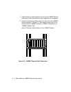
Refer to the ONline Ethernet Network Management Module Installation
and Operation Guide for information on setting redundancy between
10BASE-T Module ports.