V6000 Analog Integrated Branch Office Solution Installation Guide
23
Figure 3 V6000 Configured with Module 1 – FXS and Module 2 – FXO
1
FXS
2
FXO
I/O module
#3
CPU 1
I/O module
#4
I/O module
#5
I/O module
#6
Spare CPU
module slot
Spare
power
supply
slot
Power
supply
slot
FAN
To configure the V6000 ports, follow these 4 steps:
1 In the ‘Quick Setup’ screen, click the button Æ, adjacent to the label ‘Endpoint Phone
Number Table’; the ‘Endpoint Phone Number Table’ screen opens (see
Figure 5).
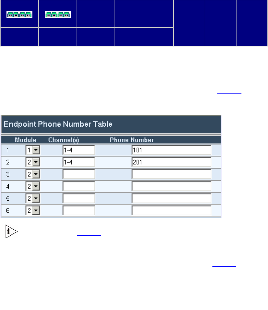
Figure 4 Endpoint Phone Number Table
In the example in Figure 5, Module #1 is FXS and Module #2 is FXO.
2 In the ‘Endpoint Phone Number Table’ screen, in the row for Module 1 (FXS), define
1-4 under column ‘Channel(s)’ and the first phone number, for example, 101,
corresponding to channel 1, under column ‘Phone Number’ (shown in Figure 5). The
phone numbers 102, 103 and 104 are automatically defined (in sequence),
corresponding to subsequent channels.
3 In the row for Module 2 (FX0), define 1-4 under column ‘Channel(s)’ and the first phone
number under column ‘Phone Number’, for example, 201, corresponding to channel 1,
under column ‘Phone Number’ (shown in
Figure 5). The phone numbers 202, 203 and
204 are automatically defined (in sequence), corresponding to subsequent channels.
4 Click the button Submit and then click Quick Setup; you’re returned to the ‘Quick Setup’
screen.


