


48 C
HAPTER
4: A
DVANCED
M
ANAGEMENT
T
ASKS
the lower-numbered backplane port. (Example: On a 10-port Layer 2
switching module, you configure port 11; on a 12-port Layer 3
module, you configure port 13.) When you have multiple VLANs, tag
the backplane port. (In a subsequent step, you must tag the
associated switch fabric module backplane port as well.)
4
On each Layer 3 switching module with VLANs that you want to perform
routing, define a routing interface for each protocol-based or
network-based VLAN. Verify that the routing interface is defined to use
the same network or subnetwork as any other module that supports the
VLAN.
5
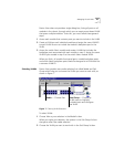
Use the EME to connect to the switch fabric module and configure all
VLANs that will pass traffic through the Layer 2 switch fabric module (that
is, VLANs that are associated with switching modules or the GEN
interface modules).
a
For each VLAN definition that is associated with one or more
switching modules, include the switch fabric module backplane ports
that correspond to the VLAN’s participating switching modules. (For
example, if the VLAN’s participating modules reside in slots 3 and 5,
include switch fabric module ports 5 and 9 in the VLAN definition on
the switch fabric module.) Tag these switch fabric module ports if the
backplane ports of the corresponding switching modules are tagged.
(For each VLAN, verify that the tagging type for a switch fabric
module port matches its associated backplane switching module
port.)
For each VLAN definition for 2-port GEN interface modules, include the
switch fabric module backplane ports that correspond to the VLAN’s GEN
interface modules. (For example, if the VLAN’s GEN interface module
resides in slot 6, you define switch fabric module ports 11 and 12 to be
part of the VLAN.) Tag these ports if the front-panel ports of the GEN
interface modules are connected to IEEEE 802.1Q enabled devices, such
as other CoreBuilder 9000 systems, CoreBuilder 3500 Layer 3 switches, or
other 3Com switches.