


9/92
4-1
MODEL 2100 OVERHEAD PROJECTOR
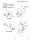
GENERAL
The following section describes the
adjustments that will be necessary to service
the Model 2100 (4100) Overhead Projectors.
TOOLS REQUIRED
A. Screwdriver (standard & phillips)
B. Wrench, open end
C. Pliers, standard
D. Pliers, grip ring
E. Square
F. Torx Driver, #T-15 (for removal of stage
glass) 3M Part Number 26-1005-8317-3
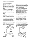
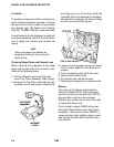
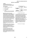
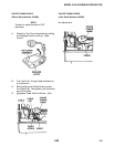
PROJECTOR CHECK-OUT FACILITIES
Reliable check-out and optical alignment of the
overhead projectors can be accomplished only
if proper facilities are available. (see Figure)
This requires a permanent viewing screen and
test stand in the dealer’s shop, thus enabling
high check-out standards to be established and
maintained. Service personnel will also find that
the use of permanent test facilities will assure a
better check-out job in considerably less time
than otherwise would be required.
Only two low-cost items are required to provide
proper check-out facilities: a test viewing
screen, 60 by 60 inches, with a flat (non-
reflective) white surface; and a bench or test
stand permanently located about 8 feet from
the screen.
The screen should be vertical and can most
easily be provided by applying a flat white paint
to a 60 by 60 inch area of a smooth wall. If a
smooth wall is not available, a piece of
wallboard painted flat white, or a white window
shade of the proper size, can be mounted in
the selected area.
The test stand should be high enough to
provide easy access to all parts of the
Overhead Projector when the projector is
placed on the stand for check-out. An electrical
outlet and a switch should be built into the test
stand to facilitate making electrical connections
to the projector.
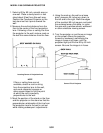
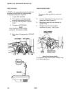
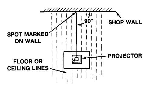
The following steps provide a simple procedure
for setting up the permanent test facilities. It is
particularly important that the projector be
perfectly square with the viewing screen in
order to eliminate the possibility of vertical or
horizontal keystoning. Even the slightest
keystoning will result in unequal focusing of the
projected image at the four corners, and will
especially affect resolution readings.
Therefore, several of the following steps involve
squaring the projected light with the screen.
Permanently locating the test stand and
viewing screen will assure that the proper
relationship, once established, does not
change.
(Continued on the next page)
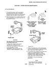
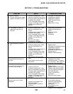
SECTION 4 ADJUSTMENTS
Arrangement of Check-out Area