


9/92
4-3
MODEL 2100 OVERHEAD PROJECTOR
OPTICAL ALIGNMENT
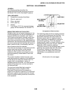
Proper alignment of the optical system is
essential for good resolution and uniform
illumination. Poor resolution in one corner and
either red or blue in the corners of the projected
image are indications of poor alignment. The
following components should be checked and
adjusted if necessary before aligning the
overhead projector.
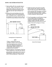
SQUARE IMAGE
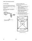
A. Set projector on a level table. Project an
image onto a screen or wall. Axis of
beam must be perpendicular to projection
surface.
B. Check to see that side of projected image
are vertical.
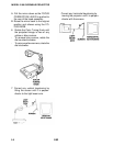
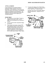
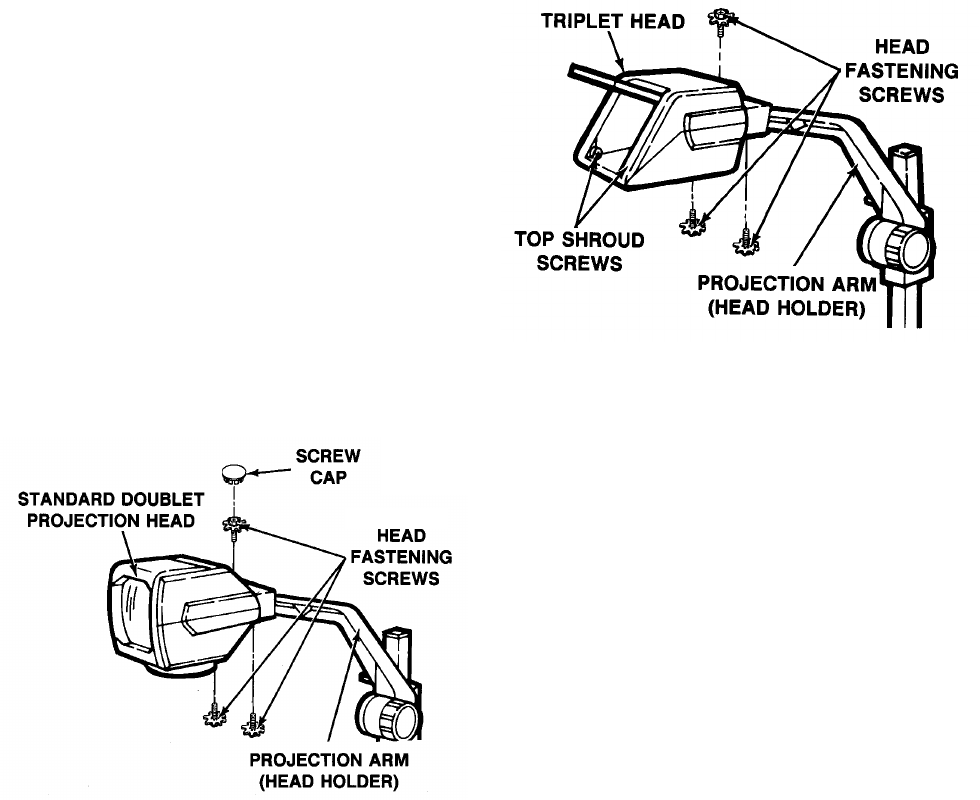
C. If the image is not square, remove CAP
and loosen the three (3) Head Fastening
Screws (Doublet Head), and move the
projection head either to the left or right,
forward or backward. When image is
square, tighten the center top screw first,
then the two bottom screws. (See Figure)
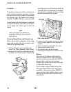
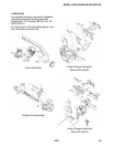
D. To square the image on the Triplet Head,
remove the two Top Shroud screws and lift
off the Top Shroud. Follow the same
procedure as used on the Doublet Head to
complete adjustment. Replace the Top
Shroud.