


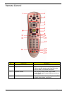

Chapter 1 11
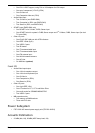
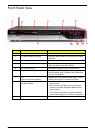
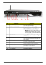
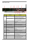
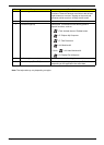
Rear Panel View
No. Component Description
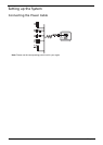
1 Power connector Plug the power cable into this connector.
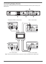
2 SCART input connector Connects to a set-top box or another A/V device.
The SCART input connector supports Video, S-
Video and Audio (L and R) input signals.
SCART input/output connector Connects to a TV or a set-top box. The SCART
input/output connector supports Video, S-Video,
Audio (L and R) input and Composite Video and
Audio (L and R) output signals.
3 IR blaster ports Connects an IR blaster to the set-top-box’s IR
sensor window.
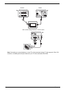
4 LAN port Connects to an Ethernet 10/100/1000MB based
network
5 TV antenna/cable output jack Connects to a television.
6 TV antenna/cable input jack Connects to an antenna or cable TV.
7 FM radio input jack Connects to an external FM radio antenna.
8 WLAN antenna connector Connects to a wireless LAN antenna.
9 Coaxial digital audio output jack Connects to a digital device, such as MiniDisc
recorders, home theater receivers, or A/V
receivers.
10 Optical digital audio output jack
11 Multi-channel speaker audio output
connectors
Connects to an amplifier which has multi-channel
audio system.
12 Video output jack Connects to a TV with video output.
13 S-Video output jack Connects to a TV with S-Video input.
14 Component video output jack Connects to a TV with YPbPr input.
15 DVI-I connector Connects to a TV or LCD with DVI input or use the
DVI-to-VGA adapter to connect a TV or monitor
with VGA (D-Sub) input.
16 HDMI Connects to a TV with HDMI input.
17 6-pin IEEE 1394 port Connects to an IEEE 1394 device (e.g., digital
video camcorder, hard disk, scanners).
18 USB 2.0 ports Connects to USB peripherals devices (e.g., USB
mouse, USB printer, USB drive).