


Machine Maintenance Procedures 3-31
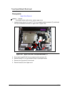
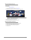
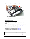
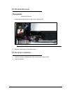
8. Remove mainboard from lower cover by pulling away from left side.
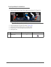
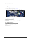
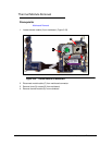
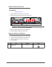
Figure 3-32. Mainboard Connectors
NOTE:
NOTE:
Connectors on left side of mainboard (i.e. USB) are set in lower cover slots. Do not
force mainboard when removing.
Mainboard Installation 0
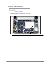
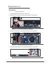
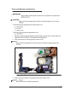
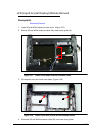
1. Install mainboard by sliding left side at a slight angle into slots on left side of lower cover.
(Figure 3-32)
NOTE:
NOTE:
Connectors on left side of mainboard (i.e. USB, etc.) are set in lower cover slots. Do not
force mainboard when trying to install it.
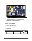
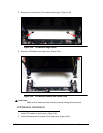
2. Lower right side of mainboard until edge is flush with lower cover. (Figure 3-31)
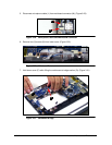
3. Install and secure two (2) screws (N) to lower cover. (Figure 3-30)
4. Connect microphone cable (L) to mainboard connector (M). (Figure 3-29)
5. Connect speaker cable (J) to mainboard connector (K). (Figure 3-28)
6. Connect LVDS cable (G) to mainboard connector (H). (Figure 3-27)
7. Connect DC-IN cable (E) to mainboard connector (F). (Figure 3-26)
8. Install function board.
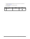
ID Size Quantity Image
D M2x3 t=0.04 2